In this example static routes are configured using the SDN controllers, in a MANET network. The MANET network model in this example consists of the following configuration:
- A subnet with 5 wireless nodes and 1 ad-hoc link, and a unicast CBR application running on one of the wireless nodes.
- DSR is the routing protocol that is enabled on all wireless nodes.
- One wireless node is configured as the SDN controller.
- Wireless nodes do not have mobility.
- A unicast application is configured from Wireless_Node_1 to Wireless_Node_5.
- Simulation time is set to 1000 seconds.
- Packet trace, and Event trace is enabled.
To simulate the example for MANET using SDN:
Open NetSim and Select Examples > Software Defined Networks > MANET StaticRoute then click on the tile in the middle panel to load the example as shown in below screenshot

The following network diagram illustrates the network setup as shown below Figure.

- DSR routing protocol is configured in Network layer for all the nodes and set the nodes to be stationary.
- Mobility model is set to NO_MOBILITY in all the nodes.
- ICMP protocol is enabled in the network layer properties of all the wireless nodes.
-
Open flow protocol is enabled in all the nodes.
The following settings were done in the wireless nodes to configure Wireless Node 4 as SDN controller and other nodes as its clients.Device Name Open_Flow SDN_Controller SDN_Controller_DeviceName Wireless_Node_1 Enable FALSE SDN_Controller Wireless_Node_2 Enable FALSE SDN_Controller Wireless_Node_3 Enable FALSE SDN_Controller SDN_Controller Enable TRUE FALSE Wireless_Node_5 Enable FALSE SDN_Controller -
Click on the Application icon present in the top ribbon/toolbar.
a. CBR Application from Wireless_Node_1 to Wireless_Node_5 with 0.584 Mbps Generation Rate (Packet Size: 1460Bytes, Inter Arrival Time: 20000µs.
b. Set Transport Protocol to UDP. - Channel Characteristics: Path Loss Only, Path Loss Model: Log Distance, Path Loss Exponent:3.2.
- In NetSim GUI Plots, Packet Trace and Event Trace are enabled.
- Simulate the example. To do so:
a. Click the Run button. The Run Simulation pop-up window appears.
b. Simulation time is set to 1000 seconds.
c. In the Run time Interaction tab, the Interactive Simulation option is set to True.
d. Click Accept.
e. Click OK.
Simulation (NetSimCore.exe) starts to run. NetSimCore.exe displays the following message: waiting for first client to connect. - To use the SDN CLI Console: a. Right-click SDN_Controller and select NetSim Console. Now, the client (NetSimCLI.exe) starts and attempts to establish a connection with NetSimCore.exe.
- Interpret the results.
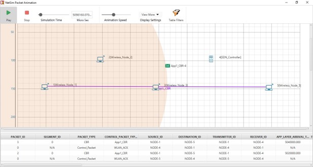
a. Click View Animation and see the Packet Animation.
The packets reach Wireless_Node_5 from Wireless_Node_1-> SDN_Controller -> Wireless_Node_5.
- Configure static routes such that the packets will go through Wireless_Node_1 > Wireless_Node_2, Wireless_Node_3, SDN_Controller to Wireless_Node_5.
To configure the static routes on SDN_Controller for all the nodes.
a. Run the simulation again.
b. Right-click SDN_Controller and select NetSim Console.
Now, the client (NetSimCLI.exe) starts and tries to establish a connection with NetSimCore.exe.
NetSim CLI console opens.
c. Type the following commands on the NetSim CLI console, in the <DeviceName with Device_ID> route add <destination IP address> MASK <subnet mask> <gateway IP address> <metric> if <interface #> format.
Wireless_Node_1 route add 11.1.1.5 mask 255.255.0.0 11.1.1.2 metric 1 if 1
Wireless_Node_2 route add 11.1.1.5 mask 255.255.0.0 11.1.1.3 metric 1 if 1
Wireless_Node_3 route add 11.1.1.5 mask 255.255.0.0 11.1.1.4 metric 1 if 1
SDN_Controller route add 11.1.1.5 mask 255.255.0.0 11.1.1.5 metric 1 if 1 - Interpret the results.
a. Click View Animation and see the Packet Animation. The packets reach Wireless_Node_5 via Wireless_Node_1 > Wireless_Node_2 > Wireless_Node_3 > SDN_Controller > Wireless_Node_5.
b. In the simulation results window select the Open Packet trace option in the left area. Once the packet trace opens apply filter in the CONTROL_PACKET_TYPE/APP_NAME column to show only OPENFLOW_COMMAND and OPENFLOW_RESPONSE messages.
You will see that OpenFlow packets flow from Wireless_Node_1 > Wireless_Node_2 > Wireless_Node_3 > SDN Controller to Wireless_Node_5 as part of the commands executed for static route configuration.