The Cognitive Radio network you model from the example configuration file meets the following specifications:
- A network with 1 base station and 2 CR CPEs, and a unicast application running on one of the CR CPEs.
NetSim uses the following defaults for this example:
- The unicast application transmits data at a constant bit-rate from CR_CPE_2 to CR_CPE_3.
- Simulation runs for 100 seconds.
- Packet trace is enabled.
To simulate the example for PU and SU’s Spectrum Usage for Cognitive Radio, in NetSim:
Open NetSim and Select Examples > Cognitive Radio Networks > PU SU Spectrum Usage then click on the tile in the middle panel to load the example as shown in below screenshot

The following network diagram illustrates what the NetSim UI displays when you open the example configuration file see Figure 4-7
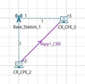
- See that by default, NetSim has set a grid length of 500m X 500m.
-
See that by default, NetSim has set the Incumbent Count to 1, the range of the operating frequency from 54 MHz to 60 MHz, and incumbent has an OFF period. To do so:
a. Right-click Base_Station_1 and click Properties. The Cr_Bs pop-up window appears.
b. Click INTERFACE_1 (COGNITIVE_RADIO) in the left area.
c. Click DATALINK_LAYER in the right area.
d. Incumbent count drop-down list is set to 1.
e. NetSim has specified a value of 54 in the Oper_Freq_Start (MHz) field
f. NetSim has specified a value of 60 in the Oper_Freq_End(MHz) field.
g. NetSim has specified a value of 10 in the ON_Duration(s) field.
h. NetSim has specified a value of 10 in the OFF_Duration(s) field.
i. Click OK. -
Ensure that the distance between incumbent and CR CPEs is less than 100m (keep-out distance).
- In NetSim GUI Plots are Enabled.
- Simulate the PU SU Spectrum Usage for Cognitive Radio example. To do so:
a. Click the Run icon located on the toolbar.
The Run Simulation pop-up window appears.
b. Retain the default settings in the Simulation Configuration tab (Simulation Time = 100).
c. Click OK. After NetSim simulates the PU SU Spectrum Usage for Cognitive Radio example, NetSim displays the Simulation Results window. - Interpret the results. To do so
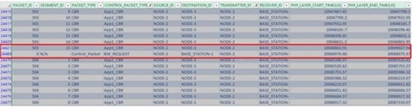
a. Click Open Packet Trace in the left area and filter the Packet_Type column by CBR and BW Request the Transmitter_ID column by Node-2 (CR_CPE_2).
b. See the filtered values in the PHY_Layer_START time column,in the spreadsheet.Observe that no data is transmitted between 10 to 20 seconds because, the incumbent user is using the channel. For thefirst 10 seconds, Node-2 uses the channel and for the next 10 seconds, the incumbent (Base_Station_1) uses the channel. And, this happens every 10 seconds. The following figure illustrates step (b)