Open NetSim and Select Examples -> Mobile Adhoc Networks -> MANET OLSR then click on the tile in the middle panel to load the example as shown in below Figure

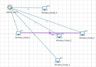
NetSim UI displays the following network when you open the example configuration file see below Figure
Settings done in the Network#
- Grid length: 500m*500m.
- A network scenario is designed in NetSim GUI comprising of 5 Wireless Nodes and one ad-hoc link in the “Mobile Adhoc Network” Network Library.
- In the General Properties set mobility Model as NO MOBILITY for all devices present in GUI
- The Medium Access Protocol was set to DCF in INTERFACE_1(WIRELESS)-> Datalink layer of all Wireless Nodes
- Configure CBR application with Transport Protocol to UDP in Application Properties
- Channel characteristics: Path loss only, Path loss model: Log Distance, Path loss exponent: 3.
- Set OLSR routing protocol under network layer properties in all nodes.
- Enable Packet Trace.
- In NetSim GUI Plots are Enabled.
- Run simulation for 30 seconds.
Output#
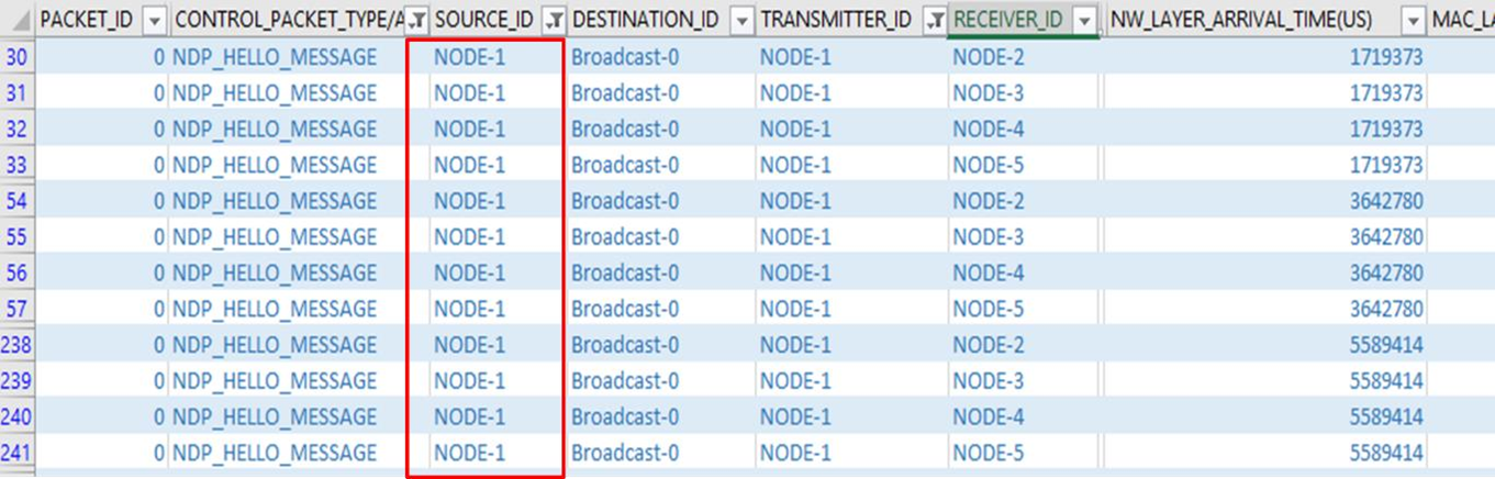
Open Packet trace and filter Control_Packet_Type/App_Name to NDP_HELLO_MESSAGE, Source_ID and Transmitter_ID to Node-1. All the nodes in the network exchange the NDP_HELLO_MESSAGEs periodically (for every 2 seconds- check NETWORK_LAYER_ ARRIVAL_TIME column) to detect the neighbours. In the below screenshot, Node-1 is broadcasting NDP_HELLO_MESSAGES to its neighbours 2, 3, 4 and 5 for every 2 seconds as shown in below Figure
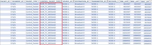
Now filter Control_Packet_Type/App_Name to OLSR_TC_MESSAGE, Source_ID and Transmitter_ID to Node-1. All nodes in the network broadcasts Topology Control (TC) messages (for every 5 seconds - check NETWORK_LAYER_ARRIVAL_TIME column) in order to build the topology information base. In the below screenshot, Node-1 is broadcasting OLSR_TC_MESSAGE to its neighbors 2, 3, 4 and 5 for every 5 seconds as shown in below Figure