Earth-Fixed Beam Pointing in a LEO Constellation
NetSim Astra · 480 LEO satellites · 17.7 GHz · 8 city targets in India
A LEO satellite at 550 km moves in its orbit at approximately 7.6 km/s. If its beam points straight down, the footprint moves with the satellite. Earth-fixed pointing (target tracking) steers each beam to a ground target. This study uses NetSim Astra to find the effect of target tracking at ground sites and in the areas around them.

Goal of the study
The study compares two pointing modes for one LEO constellation and eight ground targets.
The questions
- What received power and C/N does a ground site get with each pointing mode, and for how much of the time?
- How frequently does the serving satellite change with target tracking, and how far must each beam steer?
- Where do the steered beams come from, and which areas get no beam as a result?
The procedure
NetSim Astra does each analysis two times, with the same parameters. Only the antenna pointing changes. A coverage analysis gives a snapshot of India and the countries near it. A point analysis then follows each city for one hour.
The beam types of 3GPP TR 38.821
| Scenario | Table 4.2-1 of TR 38.821 | Astra pointing mode |
|---|---|---|
| C1, D1 | LEO based non-terrestrial access network: steerable beams | Earth-fixed (targeted) |
| C2, D2 | LEO based non-terrestrial access network: the beams move with the satellite | Earth-moving (nadir) |
TR 38.821 V16.2.0 gives the reference scenarios. Scenario C uses a transparent payload, and Scenario D uses a regenerative payload. In Table 4.2-2, the row "Earth-fixed beams" gives "Yes (steerable beams)" for C1 and D1. This study uses only the beam types. Its altitude, frequency and beam are different from the TR parameters.
Two pointing modes in NetSim Astra
Antenna pointing is a parameter of the satellite antenna. Earth-fixed pointing is available in point and coverage analyses, with multibeam off.
Earth-moving (nadir)
The beam axis points to the nadir of the satellite. At 550 km, the footprint moves over the ground at approximately 7 km/s. A ground site is in the beam only when a satellite is almost overhead.
Earth-fixed (targeted)
The beam axis points to a ground target. The footprint stays on the target until the satellite selects a different target. As the satellite moves away from the target, the steering angle from nadir increases.
- Find the targets in the steering limit and at or above the elevation limit
- Select the target with the highest elevation angle
- Steer the beam axis to that target
- Calculate the link to each ground point
NetSim Astra does these four steps for each satellite at each time step. Thus a satellite can change its target before that target goes out of its limits. If no target is in the limits, the beam is idle. Two or more satellites can point at one target, and a target can have no beam.
Astra can also select the target with the highest C/N. With no clutter loss and no atmospheric loss, the nearest target has the highest C/N and the highest elevation angle. Thus the two rules select the same target in this study. In Earth-fixed mode, the phased-array antenna model is not available.
TR 38.821 (Table 4.2-2, NOTE 1) gives beams that stay on the same points on the Earth for the visibility time of the satellite. The highest-elevation rule in Astra can change the target before the end of that time.
Scenario and parameters
The two modes use the same configuration. Only the antenna pointing changes.
| Parameter | Value in NetSim Astra |
|---|---|
| Constellation | Walker delta, 24 planes of 20 satellites (480 satellites), phase offset 0, altitude 550 km, inclination 53° |
| Start time | 2026-11-01 09:41:09 UTC |
| Frequency | 17.7 GHz: the upper end of the Ku band in IEEE Std 521 (12 to 18 GHz), and the lower edge of the Ka-band satellite downlink (17.7 to 20.2 GHz) |
| Satellite antenna | Gaussian pattern, 3 dB beamwidth 10°, peak gain 30 dBi, one beam for each satellite. Astra sets the minimum gain of this pattern 30 dB below the peak (0 dBi). |
| Satellite EIRP | 70 dBW |
| Receiver | Antenna gain 0 dBi, system noise temperature 290 K, bandwidth 10 MHz |
| Losses | 2 dB additional loss. No clutter loss and no atmospheric loss. |
| Targets | Delhi, Guwahati, Ahmedabad, Kolkata, Mumbai, Hyderabad, Chennai and Bengaluru |
| Earth-fixed parameters | Assignment rule: highest elevation. Maximum steering angle 60°. Minimum elevation angle 10°. |
| Coverage analysis | A square with 5,000 km sides and its centre at 21° N, 85° E. Grid spacing 25 km (40,401 points). Six time steps at intervals of 60 s. |
| Point analysis | Each of the 8 cities, for 1 hour from the start time. One sample at intervals of 2 s (1,801 samples). Minimum elevation 10°. |
Table 1: NetSim Astra parameters for the two pointing modes.
The link parameters are study inputs. The study compares the two modes, and the absolute levels are not a link budget. Astra calculates C/N, and it does not calculate interference between beams. Thus the C/N values apply only if each beam has its own channel. At Delhi, two or more beams point at the city in 86% of the samples.
A snapshot: the same 12 satellites in the two modes
The coverage analysis shows India and the countries near it at one time step.
Figure 1: Received power at one time step. S1 to S12 are the 12 satellites that point their beams at the cities in Earth-fixed mode. Their numbers increase with the steering angle. In the Earth-fixed panel, the satellites above the area with no colour have idle beams, because no target is in their limits.
| S1 to S12 | Earth-moving (nadir) | Earth-fixed (targeted) |
|---|---|---|
| Beams on India | 3 | 12 |
| Grid points in India at −80 dBm or more | 1.3% | 2.6% |
| Grid points in India at −85 dBm or more | 2.4% | 15.8% |
| Grid points in India at −90 dBm or more | 3.5% | 30.6% |
Table 2: Snapshot results for the same 12 satellites.
Nadir: only 3 of 12 beams on India
S1, S2 and S3 are above India. The beams of S4 to S12 fall on the countries near India and on the sea.
Earth-fixed: the beams move to the targets
All 12 satellites steer their beams to the 8 cities, with steering angles from 7.5° to 59.1°. The areas below S4 to S12, in the countries near India and on the sea, get no beam.
Large footprints at low power
At −90 dBm, the coverage of India increases from 3.5% to 30.6%. At −80 dBm, it increases only from 1.3% to 2.6%. The steered beams have large footprints, but their power is low. S9 to S12 give less than −80 dBm at all points. Also, 6 of the 12 beams point at Delhi or Guwahati, and their footprints overlap.
Received power and C/N at Delhi over one hour
This point analysis at Delhi gives one sample at intervals of 2 seconds. Each sample is from the satellite that gives the highest received power.
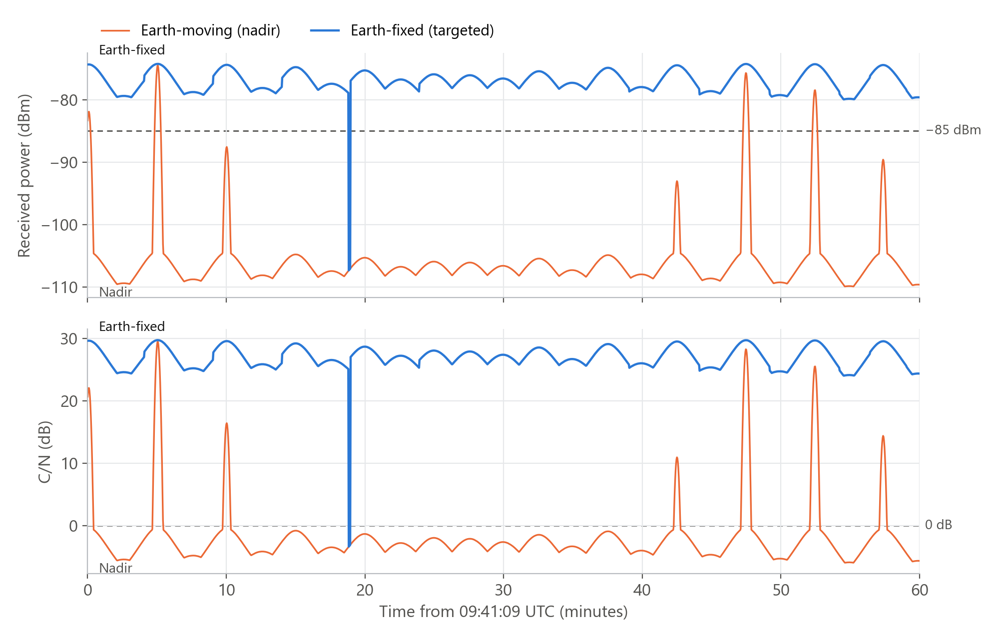
Figure 2: Received power (top) and C/N (bottom) at Delhi for 60 minutes from 09:41:09 UTC. The dashed lines show −85 dBm and 0 dB.
| Delhi, one hour | Earth-moving (nadir) | Earth-fixed (targeted) |
|---|---|---|
| Time at −85 dBm or more | 2.4% | 99.8% |
| Median received power | −107.0 dBm | −77.1 dBm |
| Median C/N | −3.1 dB | 26.9 dB |
| C/N, 5th percentile | −5.4 dB | 24.6 dB |
| Longest outage | 42 minutes | 8 seconds |
Table 3: Delhi, 1,801 samples in one hour. An outage is a time with received power below −85 dBm.
Nadir: 7 short peaks in one hour
A peak occurs when a satellite is almost overhead. In this hour, the peaks come from satellites in three orbital planes. In one plane, the interval between satellites is 4.8 minutes. Thus their peaks occur at intervals of approximately 5 minutes. Each peak stays at −85 dBm or more for 28 seconds or less.
Earth-fixed: a stable level
The received power stays between −74 and −80 dBm, with one outage. At minute 19, the elevation angle of the serving satellite becomes higher at Guwahati than at Delhi. Thus the satellite moves its beam to Guwahati. For 8 seconds, the next satellite continues to point its beam at Ahmedabad.
C/N follows the received power
With 290 K and 10 MHz, the noise power is −104 dBm. Thus the C/N is the received power plus 104 dB, for example 26.9 dB at −77.1 dBm.
Handovers with Earth-fixed pointing
This figure uses the same analysis at Delhi. Here, a handover is a change of the serving satellite between two samples that each have a beam on the city.
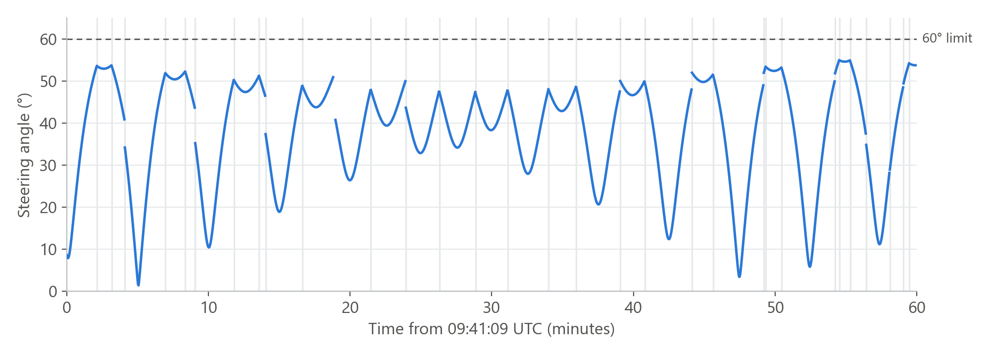
Figure 3: Steering angle of the serving satellite at Delhi. A grey vertical line shows each handover. The line stops during the outage at minute 19.
31 handovers in one hour
Delhi has 31 handovers and one outage in one hour, with 31 different satellites. Two of these satellites point their beams at Delhi two times, near the end of the hour. The time with one satellite is 106 seconds at the median, from 8 to 226 seconds.
Steering stays below 55°
The steering angle decreases while a satellite moves in the direction of Delhi, and increases after the nearest position. At minute 5, the satellite that is almost overhead has a steering angle of only 1.4°. The same satellite gives the nadir peak in Figure 2.
Two design values
The time with one satellite sets the handover rate of a terminal. This study uses no hysteresis. Thus a terminal with hysteresis can have fewer handovers. The steering angles set the scan range that the satellite antenna must have. At Delhi, the maximum steering angle is 54.9°. At five of the other cities, it is the 60° limit.
All eight cities
Each city has the same point analysis for one hour. In Earth-fixed mode, the received power is −85 dBm or more when a beam points at the city, and less at all other times.
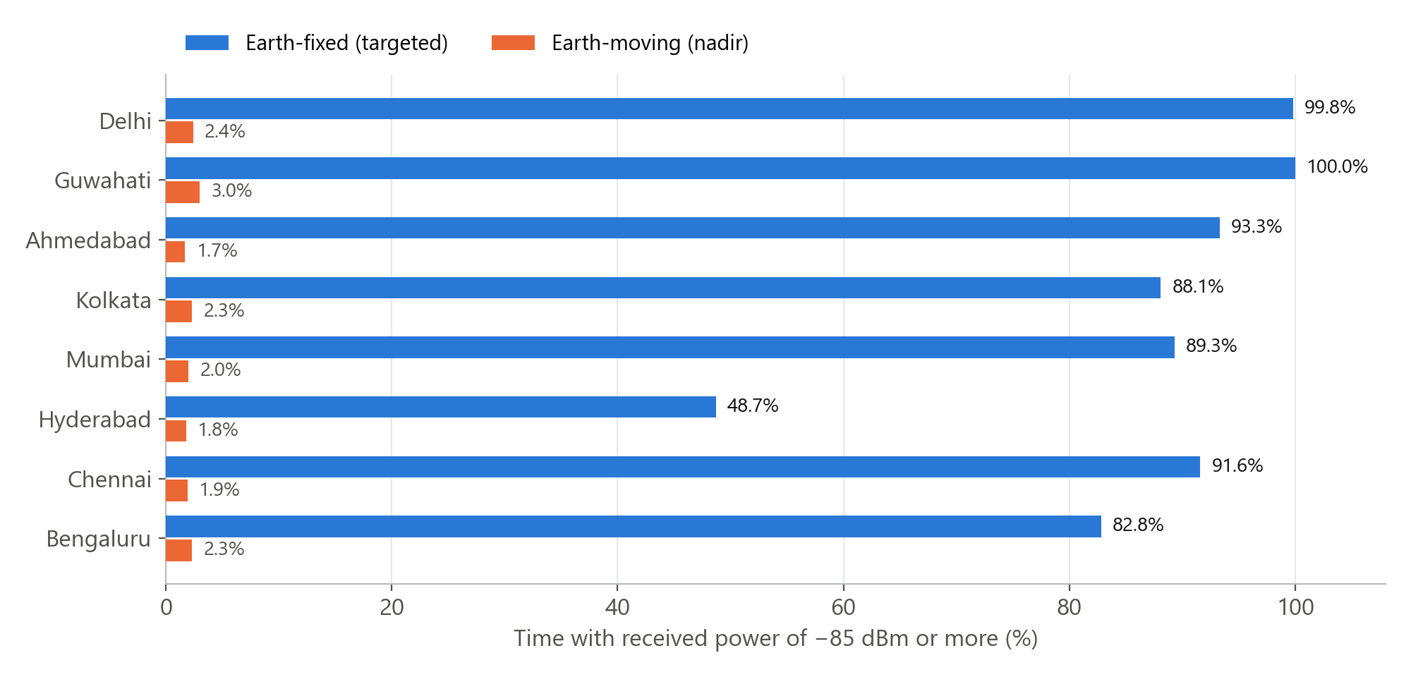
Figure 4: Time with received power of −85 dBm or more, in percent, for the 8 cities from north to south.
| City | Earth-moving (nadir) | Earth-fixed (targeted) | ||||
|---|---|---|---|---|---|---|
| Time at −85 dBm or more | Time at −85 dBm or more | Median C/N | Outages | Longest outage | Handovers | |
| Delhi | 2.4% | 99.8% | 26.9 dB | 1 | 8 s | 31 |
| Guwahati | 3.0% | 100.0% | 26.5 dB | 0 | None | 45 |
| Ahmedabad | 1.7% | 93.3% | 26.6 dB | 5 | 96 s | 30 |
| Kolkata | 2.3% | 88.1% | 26.5 dB | 17 | 50 s | 12 |
| Mumbai | 2.0% | 89.3% | 25.9 dB | 19 | 36 s | 10 |
| Hyderabad | 1.8% | 48.7% | 16.0 dB | 15 | 652 s | 6 |
| Chennai | 1.9% | 91.6% | 25.9 dB | 7 | 98 s | 24 |
| Bengaluru | 2.3% | 82.8% | 25.6 dB | 14 | 114 s | 12 |
Table 4: One hour at each city, 1,801 samples. Table 3 gives the definition of an outage. A handover is a change of the serving satellite between two samples that each have a beam on the city.
Nadir: 3% or less at all cities
With nadir pointing, each city gets −85 dBm or more for 1.7% to 3.0% of the time. Each peak continues for 28 seconds or less.
Earth-fixed: 83% to 100% at seven cities
Delhi and Guwahati almost always have a beam. At Ahmedabad, Kolkata, Mumbai, Chennai and Bengaluru, the longest outage is 36 to 114 seconds. Kolkata has 17 outages in one hour, and Mumbai has 19.
Hyderabad: 48.7%
Hyderabad has other targets on all sides. With the highest-elevation rule, a satellite selects the target nearest to its sub-satellite point. The sub-satellite points that select Hyderabad are in an area of 0.6 million km². For the other cities, this area is 1.2 to 2.4 million km². During the outages at Hyderabad, a median of 7 satellites are above 10° elevation there. Each of them steers its beam to one of the other cities, or is idle.
Geometry: range and footprint area
The geometry shows why a steered beam has a larger footprint and a lower power.
Range of a steered beam
At 550 km altitude, a steering angle of 60° gives a range of approximately 1,130 km from the sub-satellite point. At that distance, the slant range is approximately 1,300 km and the elevation angle at the target is approximately 20°. The elevation angle at the target decreases to 10° only at a steering angle of 65°. Thus in this study, the 60° steering limit sets the range.
Footprint area
In this model, the beamwidth is the same in the two modes. But a steered beam has a longer path to the ground, and a lower elevation angle at the target. The area in the 3 dB contour is approximately:
Ω is the solid angle of the 3 dB cone, 2π(1 − cos 5°) ≈ 0.024 sr. In the formula, d is the slant range and ε is the elevation angle at the target. For the 10° beam at nadir, the formula gives approximately 7,200 km².
| Satellite | Steering angle | Slant range | Elevation | 3 dB area |
|---|---|---|---|---|
| S1 | 7.5° | 556 km | 81.8° | 7,470 km² |
| S3 | 42.1° | 770 km | 43.2° | 21,150 km² |
| S6 | 53.6° | 1,021 km | 29.0° | 54,770 km² |
| S12 | 59.1° | 1,251 km | 21.2° | 120,860 km² |
Table 5: Four satellites of Figure 1 in Earth-fixed mode. The 3 dB area is the ground area in the cone of the beam, 5° from the beam axis.
The approximation agrees with these areas to 3% or less up to a steering angle of 42°. At 59°, it gives an area 14% less than the 3 dB area in Table 5. The cause is the change of the slant range and the elevation angle across the beam. At the far edge of the beam, the slant range is longer and the elevation angle is lower than at the target. The footprint of S12 is 17 times the nadir footprint.