5G/6G Non-Terrestrial Networks
LEO · MEO · GEO · Spot beams · Link budget
NetSim's NTN library is a standards-based, end-to-end, full-stack, packet-level simulator for 5G non-terrestrial networks. Model satellite links with uplink and downlink budgets, and evaluate performance across orbit heights, elevation angles, spot beams, and frequency reuse.
What you can do with it
Standards-based simulation of non-terrestrial networks, from the link budget up to end-to-end application performance.
Full-stack 5G NTN
End-to-end, full-stack, packet-level simulation of 5G NTN satellite networks.
Sweep key parameters
Evaluate performance across orbit height, elevation angle, number of spot beams, and frequency reuse factor.
Uplink & downlink budgets
Simulate uplink and downlink transmissions with full uplink and downlink link-budget calculations.
File-based mobility
Drive satellite and UE motion from CSV trajectories with time, device ID, latitude, longitude, and altitude.
Standards and architecture
The RAN follows NTN A1 mode (transparent payload) per TR 38.821, with the feeder link carrying F1 over the Satellite Radio Interface.
3GPP alignment
- TR 38.821 – NTN architecture and scenarios
- TR 38.811 – channel model
- TS 38.321 – MAC procedures (incl. Configured Grant Type 1)
Transparent payload (A1)
- RAN architecture per NTN A1 mode (transparent payload)
- Satellite Radio Interface (SRI) on the feeder link transports the F1 protocol
- NR-Uu radio interface on the service link between satellite and UE
LEO, MEO, GEO
- Configurable orbit heights with adjustable UE elevation angles
- Feeder-link SNR impairments treated as negligible per TR 38.821 Table 6.1.1.1-5; only propagation latency is modelled
Specifications
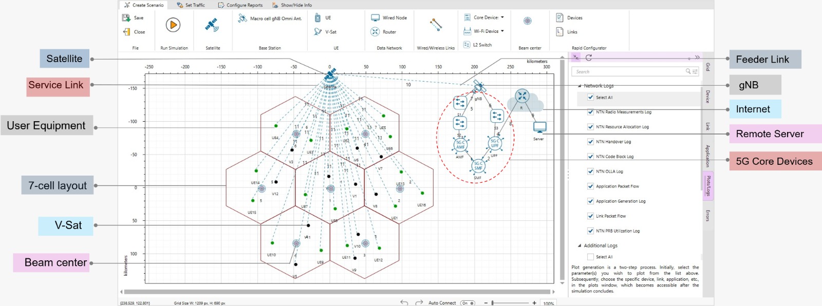
A single-satellite NTN scenario with gateway, satellite, UEs, 5G core, and remote servers, configurable from orbit down to the radio.
Network components
- Gateway, satellite, UEs, 5G core, remote servers
- gNB located outside service beams, communicating via the feeder link
- Devices: handheld in FR1; VSAT terminals in FR1 or FR2
Orbit presets & altitude
- LEO: 160–2000 km (presets 600 km, 1200 km)
- MEO: 2000–35876 km (presets 10000 km, 20000 km)
- GEO: 35786 km (fixed)
Spot beam configuration
- Fixed-earth spot beams, one-to-one with terrestrial cells
- Layouts of 1, 7, or 19 beams, plus custom beam drops
- Frequency reuse factor: FRF 1, 2, 3, 4
- Inter-site distance derived from beam diameter for hexagonal tessellation
Scenario setup modes
- Standard setup: predefined parameters per 3GPP standards
- Custom Excel/CSV: user-supplied beam configuration file
- Manual placement: user places devices and beams
Supported bands
- FR1 (3GPP Rel 17): n254, n255, n256
- FR2 (3GPP Rel 18): n510, n511, n512
Link budget calculations
- Per TR 38.821 Section 6.1.3.1
- Circular aperture reflector satellite antenna pattern
- Configurable: altitude, environment, LOS probability, antenna, EIRP, elevation angle, interference, shadow fading
Uplink scheduling
Configured Grant Type 1 enables periodic uplink transmissions without a dynamic grant per transmission, cutting control overhead and improving uplink efficiency.
Antenna models
- 3GPP TR 38.811 (gains per Section 6.4.1)
- ITU-R S.672
- Gaussian antenna model
Propagation models
- Free space path loss, atmospheric loss, clutter loss
- Shadow margin, scintillation loss, additional losses
- MCS mapping based on SINR and channel configuration
Interference modelling
- CIR-based interference model
- Exact geometric interference model
Measurements & analytics
- Throughput, latency, error, and more
- Network-wide, per beam/cell, and per application metrics
- Detailed packet trace
Logs and outputs
- NTN Radio Measurement Log: per-TTI slant height, elevation, EIRP, path/shadow/clutter/ total loss, antenna gains, Rx power, SNR, SINR, noise, interference, CQI, MCS
- NTN UE Beam Association Log: selection, tracking, reassociation
- NTN Resource Allocation Log: per-slot PRB, MCS, transport block size
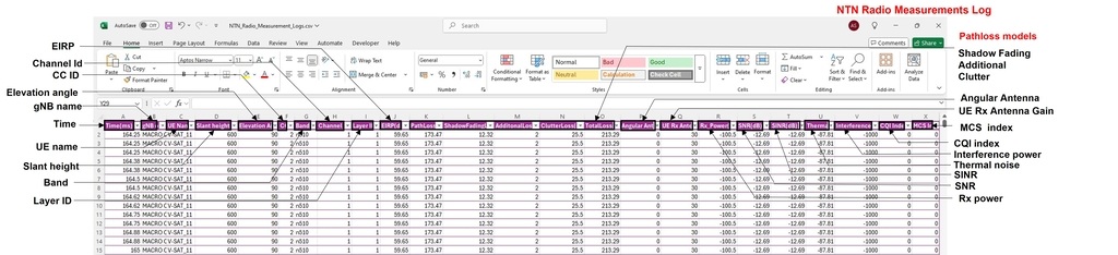
The NTN radio measurement log records the full link budget per TTI.
Featured examples
Worked NTN studies with simulated results, ready to load and extend.
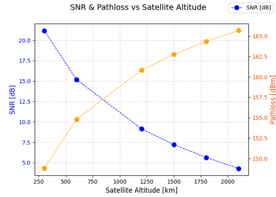
LEO altitude vs SNR and path loss
Across S-band (2.185 GHz, handheld) and Ka-band (18.75 GHz, VSAT), path loss rises with altitude. Ka-band has higher path loss yet higher SNR, thanks to the 30 dBi VSAT antenna gain.
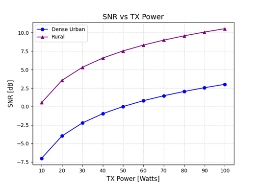
SNR vs transmit power, rural and urban
SNR rises with EIRP and Tx power in both environments. Rural is consistently higher; dense urban needs more power or beamforming to match it, due to clutter and NLOS.
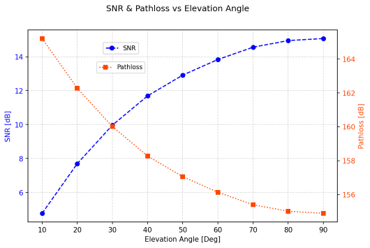
SNR vs elevation angle
In an S-band downlink at 600 km, a lower elevation angle increases slant distance, which raises path loss and reduces SNR.
Worked application
3GPP TR 38.821 reference scenario
Build and run the System Level Simulator reference scenario from TR 38.821 in NetSim: orbit, beams, link budget, and end-to-end performance, configured to the 3GPP baseline.
Related product
Satellite link budget & coverage planning
Where the NTN library simulates the network, NetSim Astra plans the constellation: satellite link budgets and RF coverage studies over real geography. Use the two together to move from coverage design to end-to-end performance.
- Satellite link budget computation
- RF coverage and footprint studies
- Geographic constellation planning
Extensions
The NTN library connects to NetSim's wider research capabilities.
Cyber attacks
See cyber security for the network attacks supported in our other libraries. Most can be ported to NTN with minor code modifications.
AI/ML in the loop
Reinforcement learning examples: 5G DL power control using RL and delay-constrained throughput maximization.
Assumptions and limitations
What the current NTN library does not yet model.
- Inter-satellite communication is not available
- HARQ disabled at gNB and UE
- RLC UM mode only
- O-RAN CU-DU-RU split is not modelled
- Terrestrial–NTN coexistence and handovers not currently available
- Perfect Doppler compensation assumed in the devices
Useful links
Documentation, a reference scenario, and support to take an NTN project further.