Using the Protocol-Specific Attacker UIs
Purpose and Scope
This section explains how to operate the protocol-specific attacker interfaces supplied with NetSim Cyber for IEEE C37.118 Synchrophasor, Modbus TCP, IEEE 1815/DNP3, and IEC 60870-5-104. It covers the available attack workspaces, target discovery, attack activation, and safe shutdown.
The procedures assume that the correct simulator is running, protocol traffic passes through NetSim Cyber, and the attacker application matches the protocol used by the experiment.
Synchrophasor Attacker
The IEEE C37.118-2005 and IEEE C37.118.2-2011 attacker windows use the same layout and operating model. Both provide Automatic, Manual, and Replay tabs. The instructions below apply to both profiles.
Configuration Discovery
Station and phasor targeting depends on configuration information observed from the PMU-PDC stream. If the UI reports that no phasor configuration is loaded, generate or request a configuration frame while NetSim Cyber is in the communication path, then reload the available targets.
Automatic Mode
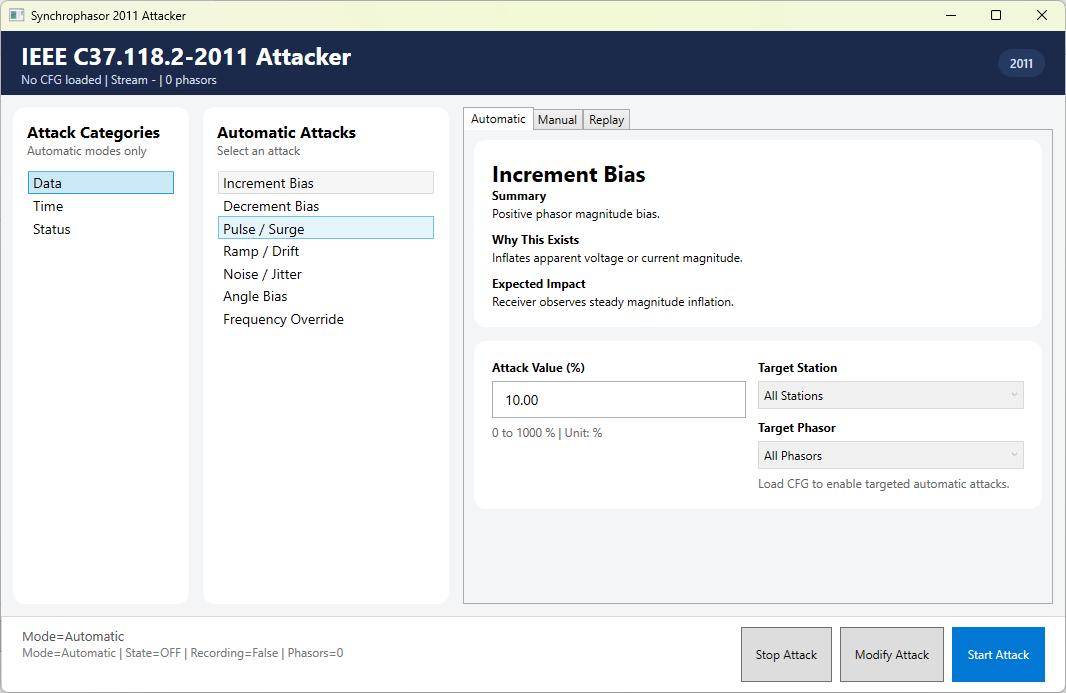
Synchrophasor Automatic tab showing the attack categories, attack list, and controls for Increment Bias.
| Attack | Purpose | Applicable target | Required UI inputs |
|---|---|---|---|
| Increment Bias | Raise selected phasor magnitudes. | Station/phasor | Attack Value, Window Size |
| Decrement Bias | Lower selected phasor magnitudes. | Station/phasor | Attack Value, Window Size |
| Pulse / Surge | Apply periodic magnitude surges. | Station/phasor | Attack Value |
| Ramp / Drift | Change magnitudes progressively. | Station/phasor | Attack Value, Direction, Window Size, optional Max Offset |
| Noise / Jitter | Add random measurement variation. | Station/phasor | Noise Type, Attack Value, probability controls |
| Angle Bias | Offset the selected phasor angle. | Station/phasor | Attack Value in degrees |
| Frequency Override | Replace the frequency field. | Selected stream | Attack Value in Hz |
| Time Sync (SOC) | Shift the whole-second timestamp. | Selected stream | Attack Value in seconds |
| Fine Time Shift | Shift the sub-second timestamp. | Selected stream | Attack Value in microseconds |
| STAT Sync Error | Set the synchronization-error status. | Selected stream | Bit Value |
| STAT Data Modified | Set the data-modified status. | Selected stream | Bit Value |
| STAT Config Changed | Set the configuration-changed status. | Selected stream | Bit Value |
| Time Quality Corruption (2011 only) | Change the FRACSEC time-quality value. | Selected 2011 stream | Attack Value from 0 to 15 |
Packet Attack Probability is available for eligible automatic attacks. Target Station and Target Phasor become usable after the configuration frame has been observed.
Select a category and attack.
Choose the target station and phasor when the selected attack supports targeting.
Set the attack value and any attack-specific controls.
For noise attacks, select Proportional Range, Gaussian, Uniform, or Spike behavior.
Set packet attack probability, window size, ramp direction, or maximum offset when those controls apply.
Review Config Preview and select Start Attack.
Use Modify Attack to update an active configuration or Stop Attack to disable it.
Manual Mode
Synchrophasor Manual tab with the phasor list loaded from the configuration frame.
Select Reload Phasors if the target list is empty or configuration data has changed.
Enable the required phasor rows.
Enter replacement magnitude and angle values.
Optionally enter Frequency Override and ROCOF Override values.
Select Apply Manual Values.
Select Clear Manual when the test is complete.
Replay Mode
Synchrophasor Replay tab with recording, CSV selection, replay, and stop controls.
Replay mode records live phasor values or replays values from a CSV file. Replay data can include magnitude, angle in degrees, frequency, and ROCOF.
Select the replay CSV path when using a prepared dataset, or start recording live values.
Allow enough normal data to be recorded for the intended test.
Start replay and monitor the Replay Preview and runtime status.
Select Stop when the scenario is complete.
Profile Difference
The 2005 and 2011 attacker UIs use the same workflow. The 2011 profile additionally provides Time Quality Corruption in the Time category.
Modbus TCP Attacker
The Modbus TCP attacker modifies selected slave responses after supported master requests. It provides Automatic, Manual, and Replay tabs.
Automatic Mode
Modbus TCP Automatic tab showing Increment Bias and its target and parameter controls.
| Attack | Purpose | Applicable target | Required UI inputs |
|---|---|---|---|
| Increment Bias | Raise values relative to their observed range. | FC03/FC04 registers | Bias Level, Window Size |
| Decrement Bias | Lower values relative to their observed range. | FC03/FC04 registers | Bias Level, Window Size |
| Offset Bias | Add a fixed signed value. | FC03/FC04 registers | Offset Value |
| Ramp / Drift | Change values progressively. | FC03/FC04 registers | Drift Rate, Direction, Window Size, optional Max Offset |
| Noise / Jitter | Add configurable random variation. | FC03/FC04 registers | Noise Type, noise value, probability controls |
| FDI (Overwrite Value) | Replace values with a fixed number. | FC03/FC04 registers | Injected Value, encoding, byte order |
| Bit Force ON | Force selected bits to logic 1. | FC01/FC02 bits | Target scope/signal |
| Bit Force OFF | Force selected bits to logic 0. | FC01/FC02 bits | Target scope/signal |
| Bit Toggle | Invert selected bits across responses. | FC01/FC02 bits | Target scope/signal |
Select an attack from the Attack Catalog.
Choose the target scope and, when available, a discovered target signal.
Enter the attack value and attack-specific parameters.
For register attacks, select FLOAT32 or UINT16 encoding and the required byte order: ABCD, CDAB, BADC, or DCBA.
Review Config Preview and select Start Attack.
Use Apply Changes to update an active attack or Stop Attack to disable it.
Manual Mode
Modbus TCP Manual tab with an observed FC04 address range and editable register rows.
Manual mode targets addresses discovered from valid Modbus read traffic. It supports FC01, FC02, FC03, and FC04 response modification.
For FC03 and FC04, enable the required rows and enter replacement register values.
For FC01 and FC02, enable the required rows and choose ON, OFF, or TOGGLE.
Use Select All or Clear to manage the visible address rows.
If no observed range is available, first generate normal master-slave read traffic.
Replay Mode
Modbus TCP Replay tab showing the recording and replay workflow.
Replay mode records supported Modbus read responses and replays the recorded sequence.
Choose all supported read responses or a specific function code: FC01, FC02, FC03, or FC04.
Select Start Recording while the required Modbus traffic is active.
Stop recording after sufficient responses have been captured.
Select Start Replay to use the recorded response sequence.
Select Stop Replay or Reset when the scenario is complete.
Troubleshooting
| Symptom | Likely cause | Operator action |
|---|---|---|
| No Modbus address range | No supported read traffic observed | Run normal FC01-FC04 traffic, then reopen or refresh Manual mode. |
| No phasor targets | CFG information not observed | Generate or request CFG while NetSim Cyber is in the PMU-PDC path, then reload phasors. |
| Attack has no visible effect | Wrong target, encoding, profile, or inactive configuration | Check target selection, preview, encoding/profile, and runtime status. |
| Unexpected values remain | A previous mode is still active | Stop the attack or replay, clear manual values, and confirm inactive status. |