Featured Example: IEEE C37.118 Synchrophasor Protocol
This section demonstrates the IEEE C37.118-2005 Synchrophasor workflow using the built-in PMU simulator, built-in PDC simulator or OpenPDC destination, and a NetSim Cyber Threat Agent placed in the communication path. NetSim Cyber also supports IEEE C37.118.2-2011 using the corresponding 2011 PMU/PDC simulators and attacker profile; however, the step-by-step walkthrough and results shown in this section use the 2005 profile.
IEEE C37.118 Standard Background
IEEE C37.118 defines communication and measurement requirements for synchrophasor systems used in wide-area monitoring and control. A PMU publishes time-synchronized phasor measurements, and a PDC receives, aligns, validates, and visualizes the stream.
The featured experiment uses IEEE C37.118-2005. NetSim Cyber also supports IEEE C37.118.2-2011, where the measurement and communication requirements are separated more clearly. For both profiles, the first configuration frame is critical because it describes the stream layout, phasor names, data fields, scaling information, and PMU/PDC identifiers required by the attacker UI.
Data frames carry the live phasor, frequency, ROCOF, analog, and digital measurements.
Configuration frames describe how the data frames must be parsed.
Header frames carry human-readable station or stream information.
Command frames are used by the PDC to control PMU data transmission.
Supported Synchrophasor Profiles in NetSim Cyber
| Profile | Source Simulator | Destination | Attack Support |
|---|---|---|---|
| IEEE C37.118-2005 | PMU-2005.pyw | PDC-2005.pyw or OpenPDC | 2005 Synchrophasor attacker |
| IEEE C37.118.2-2011 | PMU-2011.pyw | PDC-2011.pyw or OpenPDC | 2011 Synchrophasor attacker |
The remaining procedure uses the IEEE C37.118-2005 row from this table. For 2011 validation, select the 2011 PMU, 2011 PDC or OpenPDC configuration, and the 2011 Synchrophasor attacker profile.
OpenPDC Reference
OpenPDC setup steps are not repeated in this example. Refer to the official OpenPDC documentation and installer package when OpenPDC is used as the destination PDC.
OpenPDC project and documentation: https://github.com/GridProtectionAlliance/openPDC
OpenPDC Windows installer package: https://github.com/GridProtectionAlliance/openPDC/releases/download/v2.9.148/Synchrophasor.Installs.zip
After extraction, run openPDCSetup.msi to install OpenPDC Manager.
NetSim Cyber Architecture
The featured setup uses a distributed three-system arrangement. System 1 generates PMU traffic, System 2 runs NetSim Cyber and the Threat Agent, and System 3 receives the stream using a PDC or OpenPDC. NetSim Cyber bridges the live traffic path and applies protocol-aware payload manipulation or timing attacks.
System 1: PMU source simulator generating IEEE C37.118 traffic.
System 2: NetSim Cyber host with Real Nodes, network path, application filter, and Threat Agent.
System 3: PDC destination using the built-in PDC viewer or OpenPDC.
Distributed Synchrophasor experiment architecture with PMU source, NetSim Cyber Threat Agent, and PDC destination.
Important Synchrophasor Run Order
For Synchrophasor experiments, NetSim Cyber must be running and the Synchrophasor attacker must be ready before PMU-PDC traffic starts. The attacker learns the stream layout from the first configuration frame. If the PMU and PDC complete their initial handshake before NetSim Cyber is ready, the phasor list may not load correctly.
Demonstrated Attack Modes in This Example
In this example, we show Increment Bias, Decrement Bias, Ramp/Drift, Noise/Jitter, Frequency Override, and Manual Injection. These modes are selected because their effect can be observed directly at the PDC destination without adding extra setup steps.
Experimental Procedure
The sequence is important for Synchrophasor experiments because the attacker must capture the initial configuration frame before PMU data transmission begins.
Prepare the Distributed Systems
Step 1: Connect all systems to the same LAN and verify reachability using ping.
Step 2: Launch NetSim Cyber on System 2.
Step 3: Run NetSimCyberClient.exe as Administrator on both the source and destination systems when using the distributed workflow.
NetSimCyberClient.exe connected to the NetSim Cyber host. Run this client on both the source and destination systems so NetSim Cyber can configure the communication gateway automatically.
Note: If required, the same communication path can also be prepared manually by configuring static routes on the endpoint systems so traffic is forwarded through the NetSim Cyber system.
Step 4: Confirm that the source and destination Real Nodes appear in the NetSim Cyber topology.
NetSim Cyber topology showing the PMU source and PDC destination Real Nodes connected through the network path.
Configure NetSim Cyber
Step 1: Place the Threat Agent in the communication path between the source and destination.
Threat Agent placed in the communication path between the PMU source and PDC destination.
Step 2: Configure the Application Traffic Filter from the top ribbon by selecting the PMU source, PDC destination, and TCP port used by the Synchrophasor traffic.
Application Traffic Filter configured for the PMU-to-PDC traffic stream and protocol TCP port.
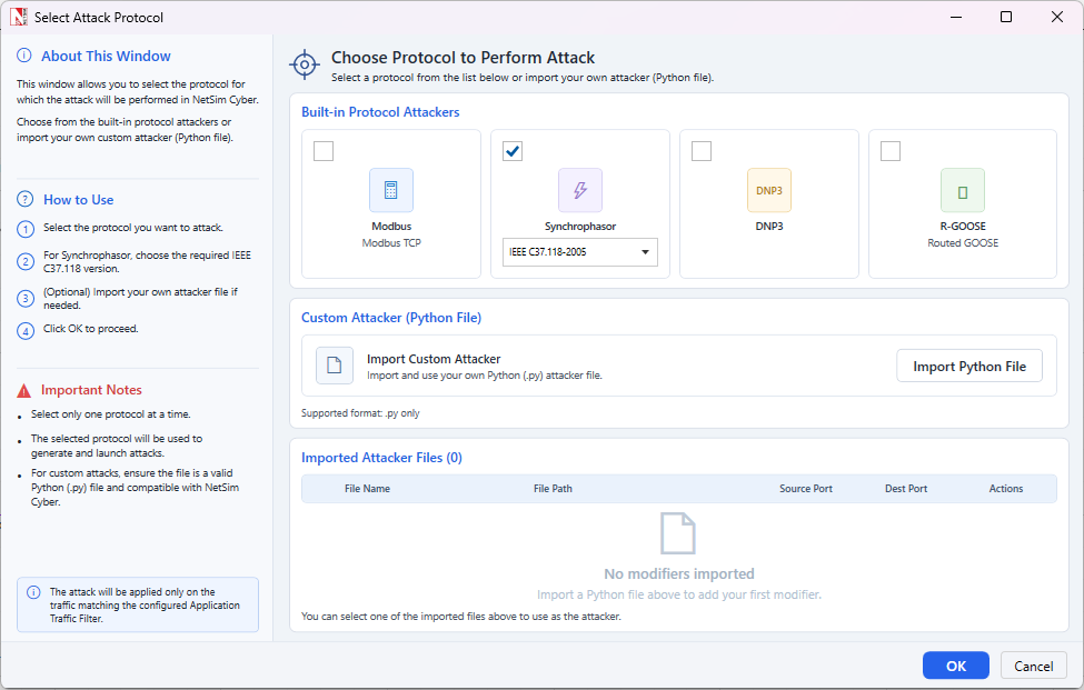
Step 3: Select the Synchrophasor attacker and choose the IEEE C37.118-2005 profile for this example.
Built-in Synchrophasor attacker selection. The 2005 profile is used for this walkthrough.
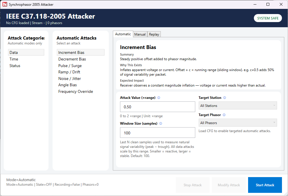
Step 4: Run the NetSim Cyber simulation and keep the attacker dashboard ready.
IEEE C37.118-2005 attacker dashboard showing automatic, manual, and replay attack modes.
Start PMU-PDC Traffic and Apply Attack
Important: keep NetSim Cyber and the IEEE C37.118-2005 attacker dashboard ready before PMU-PDC communication starts, because the attacker must capture the first configuration frame.
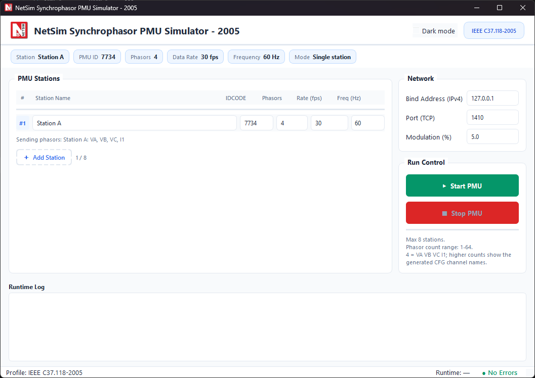
Step 1: Open and configure the IEEE C37.118-2005 PMU simulator, but do not start PMU traffic yet.

PMU simulator configuration screen showing station, PMU ID, port, and run controls. For this walkthrough, use the IEEE C37.118-2005 PMU simulator.
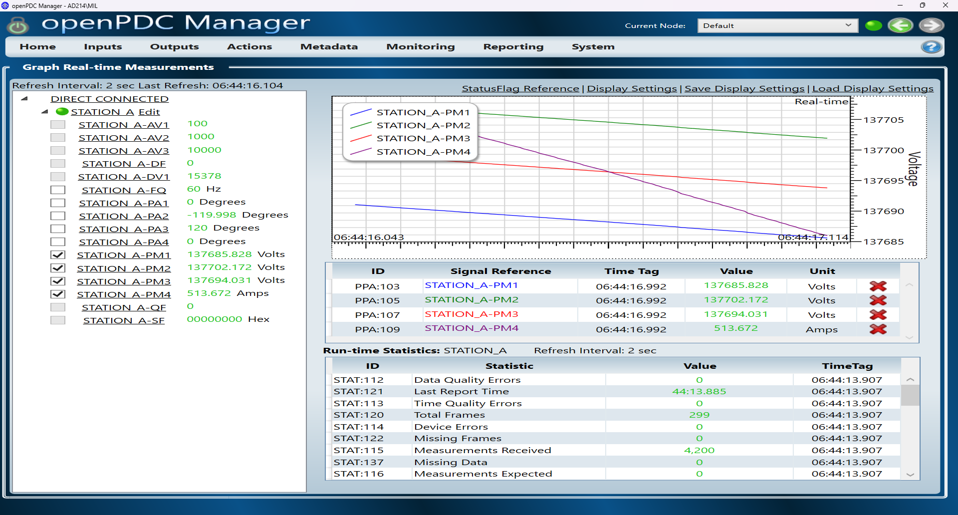
Step 2: Start the PMU simulator only after the NetSim Cyber simulation and attacker dashboard are ready, then connect the built-in PDC simulator or OpenPDC Manager to the PMU stream.
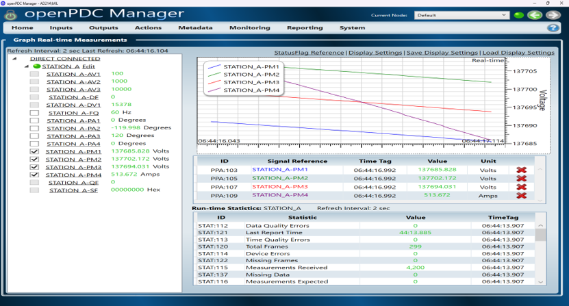
PDC or OpenPDC destination receiving and visualizing the live Synchrophasor measurement stream from the PMU.
Step 3: Verify that live measurements are displayed at the PDC and that the attacker UI has loaded the stream and phasor mapping from the first configuration frame.
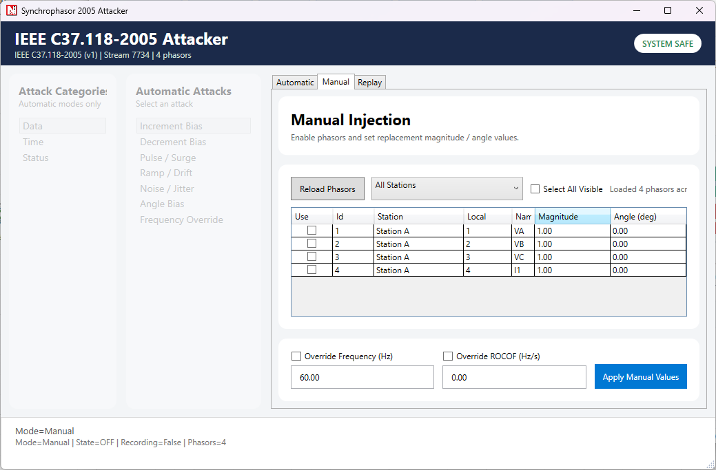
Manual injection view used after the phasor list is loaded from the first configuration frame.
Step 4: Apply the selected automatic attack or manual injection and observe the changed values at the PDC destination.
Results and Analysis
This section compares the baseline PDC measurements with the measurements observed after applying selected IEEE C37.118-2005 attacks. Each result figure shows the effect visible at the PDC or in the attacker interface while the PMU-PDC communication stream remains active.
Baseline Operation
During normal operation, the PDC receives a stable Synchrophasor stream from the PMU simulator. The baseline view is used as the reference for comparing the attack results.

Baseline PDC measurements before attack activation.
Increment Bias Attack
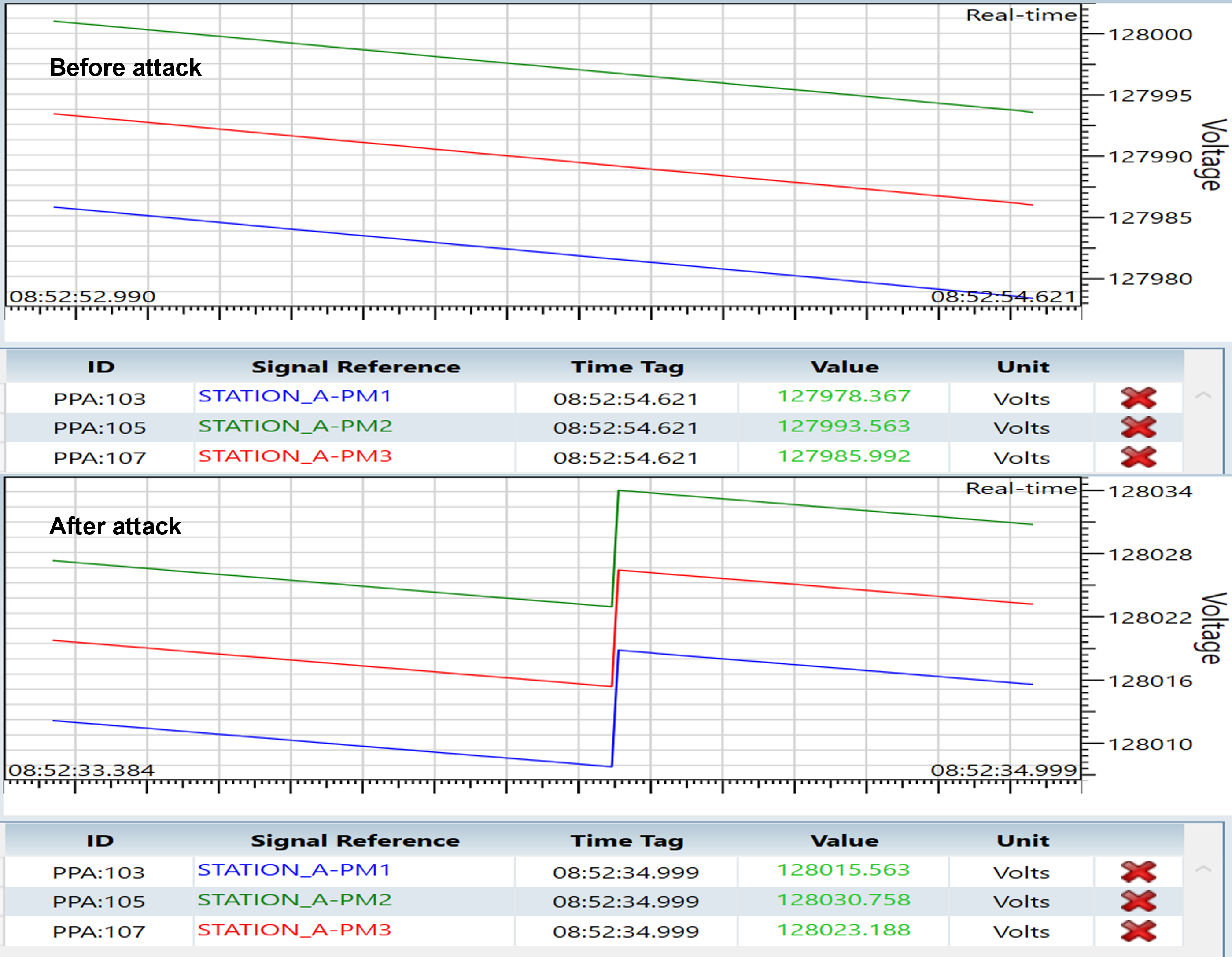
The Increment Bias attack adds a positive offset to selected phasor magnitude values. In the result, the selected PMU measurements increase at the PDC while the Synchrophasor stream remains connected.
PDC measurements before and after applying the Increment Bias attack.
Decrement Bias Attack
The Decrement Bias attack subtracts an offset from selected phasor magnitude values. In the result, the selected PMU measurements decrease at the PDC without interrupting the communication stream.
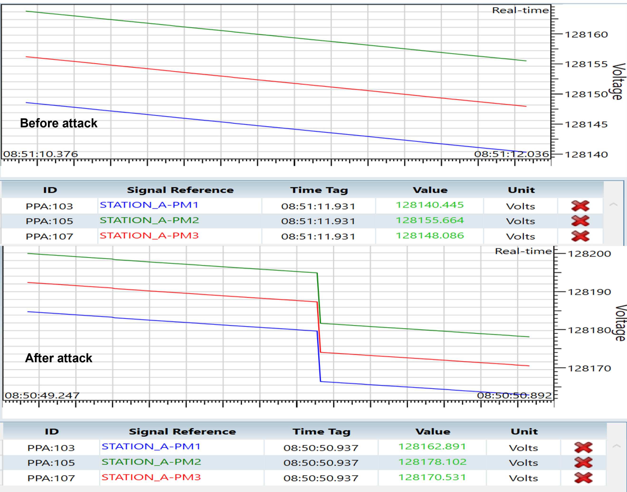
PDC measurements before and after applying the Decrement Bias attack.
Ramp / Drift Attack
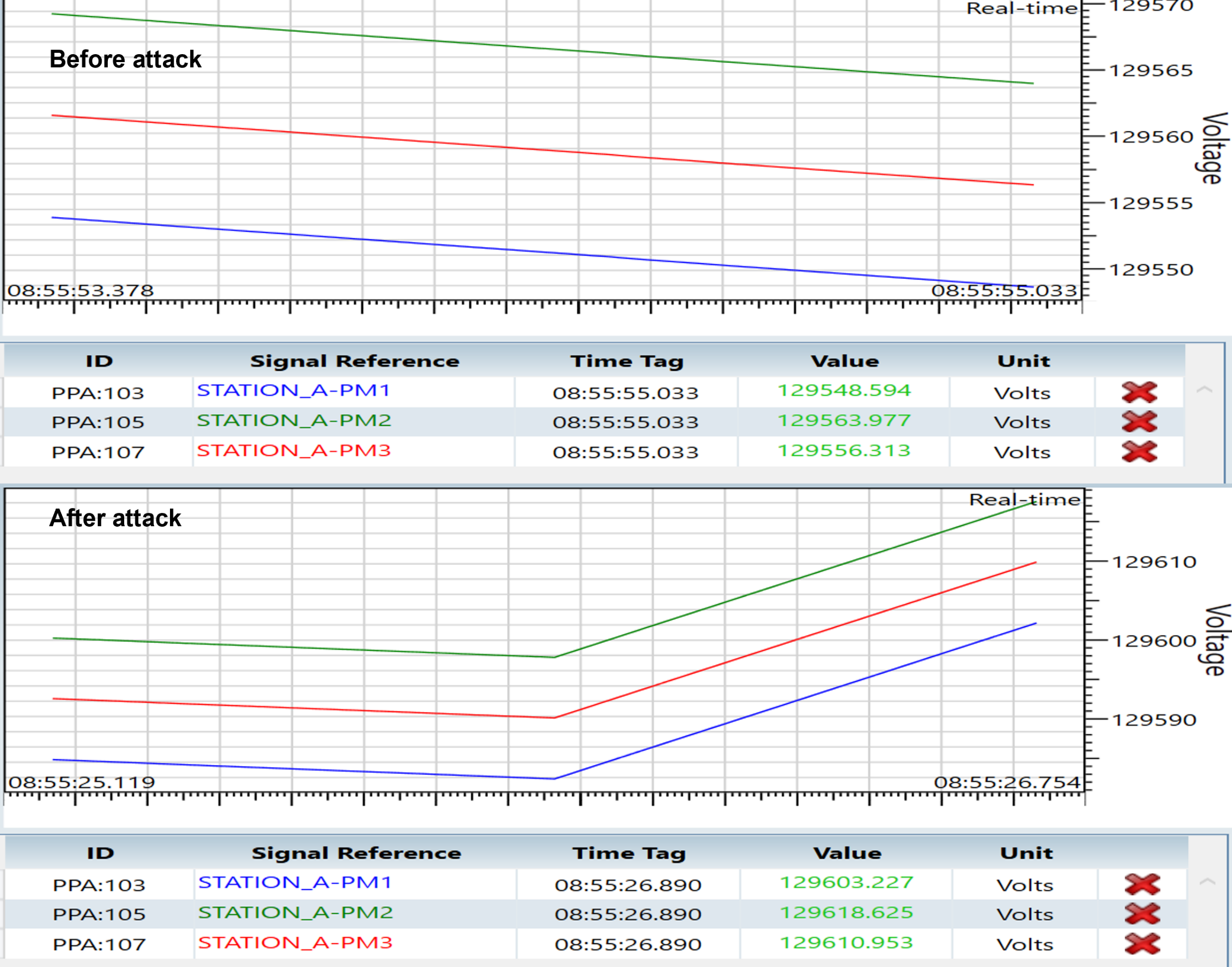
The Ramp / Drift attack gradually changes selected phasor magnitude values over time. The result shows a progressive change in the plotted measurements, resembling slow sensor drift or load variation while the protocol stream remains valid.

PDC measurements before and after applying the Ramp / Drift attack.
Noise / Jitter Attack
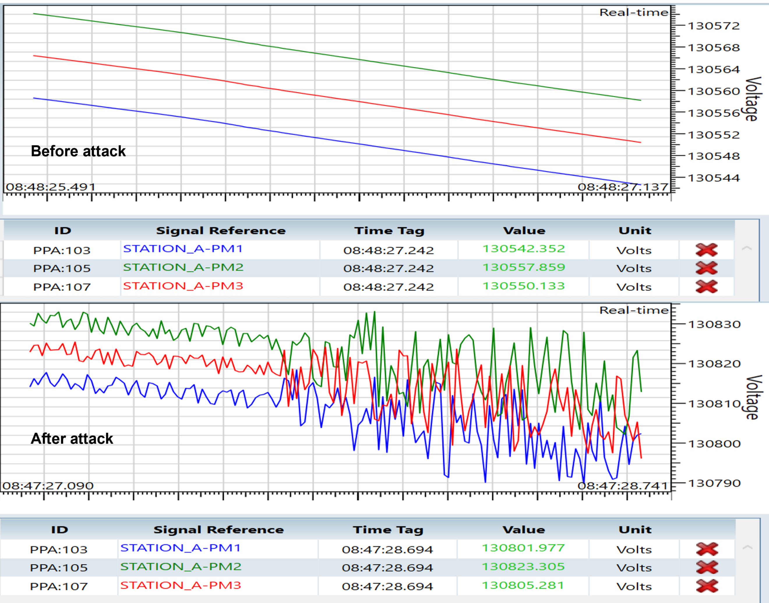
The Noise / Jitter attack adds random variation to selected phasor magnitude values while keeping the communication stream active. The result shows unstable measurement traces at the PDC, which can be used to evaluate measurement-quality monitoring and anomaly-detection logic.

PDC measurements before and after applying the Noise / Jitter attack.
Frequency Override Attack
The Frequency Override attack replaces the frequency value in the Synchrophasor data frame. The result shows the PDC frequency measurement changing from the baseline value to the injected value while the stream remains connected.
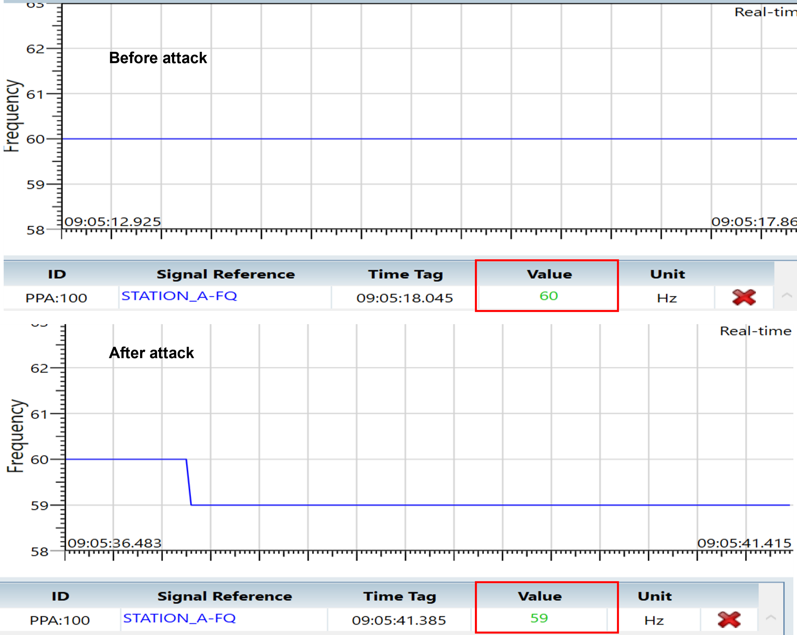
PDC frequency measurement before and after applying the Frequency Override attack.
Manual Injection
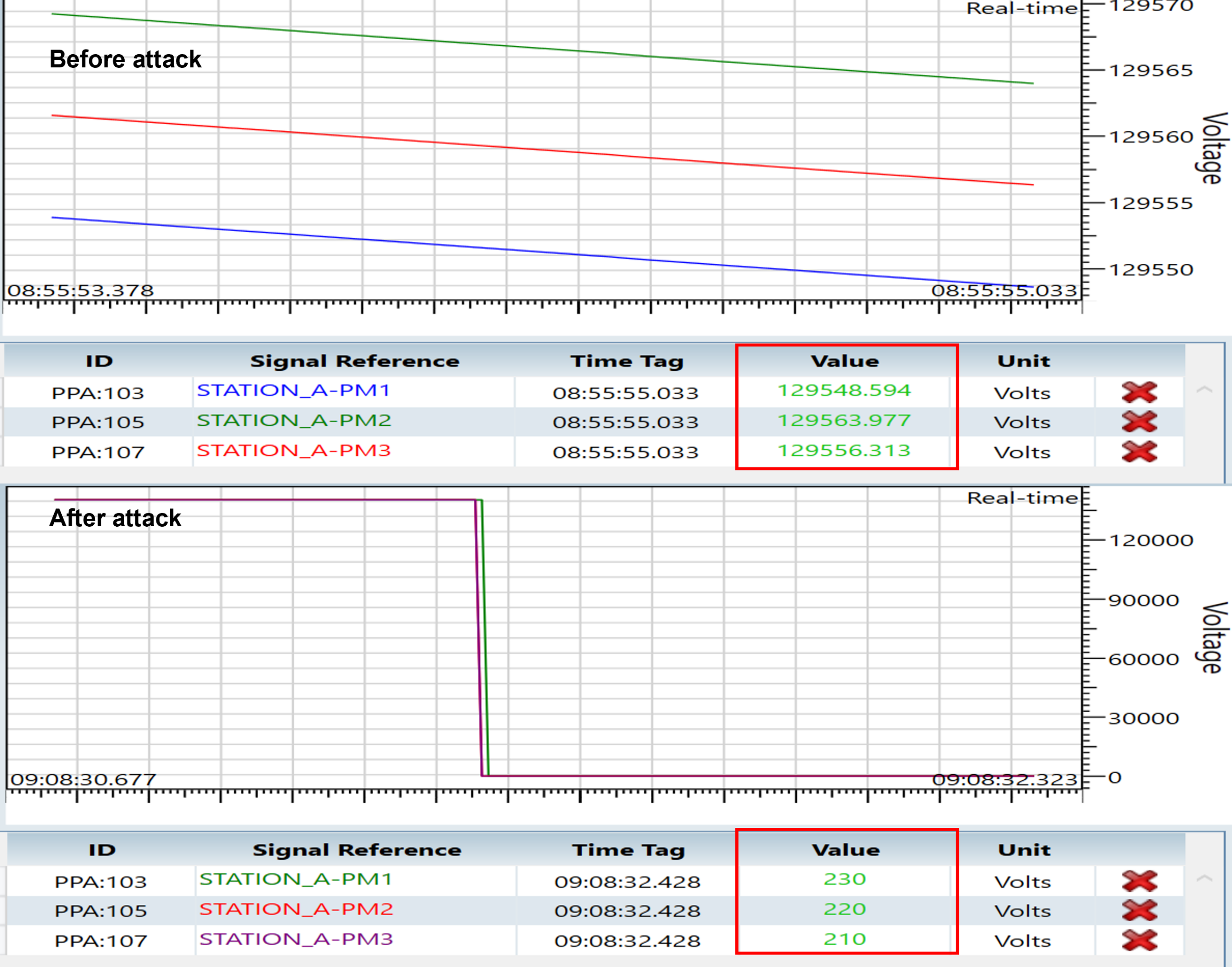
Manual Injection allows selected phasor magnitude, angle, frequency, or ROCOF values to be entered directly after the phasor list is loaded from the first configuration frame. The result shows user-defined measurement values appearing at the PDC for the selected fields.

PDC measurements before and after manual injection of selected Synchrophasor values.
Key Observations
NetSim Cyber can intercept and modify live IEEE C37.118 traffic between PMU and PDC endpoints.
This walkthrough uses the IEEE C37.118-2005 profile; the 2011 profile is supported as a separate variant.
The first configuration frame must be captured so the attacker UI can load the stream layout and phasor list.
The example focuses on increment, decrement, ramp/drift, noise/jitter, frequency override, and manual injection effects at the PDC destination.
OpenPDC can be used as the PDC destination, but detailed OpenPDC setup is referenced externally instead of repeated in this example.