Attack Library
The NetSim Cyber Attack Library provides a set of configurable cyber-attack models for power-system communication protocols. These attacks are used to study how manipulated, delayed, replayed, or dropped communication traffic can affect monitoring, protection, control, and situational-awareness applications.
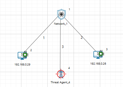
NetSim Cyber attack processing flow
The attacks described in this section are applied by the NetSim Cyber Threat Agent. The Threat Agent intercepts selected protocol traffic, applies the configured attack logic, and forwards the resulting packet stream to the destination device or application.
The Attack Library supports both signal-level attacks and network/protocol-level attacks. Signal-level attacks modify measurement values such as voltage, current, frequency, or analog data. Network/protocol-level attacks affect packet timing, packet delivery, protocol fields, or payload contents.
| Attack Type | Attack Category | Typical Target | Example Protocols |
|---|---|---|---|
| Noise Injection | Signal-level attack | Voltage, current, analog values | IEEE C37.118, Modbus, DNP3 |
| Increment / Decrement | Signal-level attack | Measurement values, register values | IEEE C37.118, Modbus, DNP3, IEC-104 |
| Ramp Attack | Signal-level attack | Gradually changing measurements | IEEE C37.118, Modbus, DNP3 |
| Pulse / Surge Attack | Signal-level attack | Short-duration measurement spikes | IEEE C37.118, Modbus, DNP3 |
| Frequency and ROCOF Attack | Synchrophasor-specific attack | Frequency and ROCOF fields | IEEE C37.118 |
| Time Synchronization Attack | Timing/data-integrity attack | Timestamp fields | IEEE C37.118, IEC-104, DNP3 |
| Replay Attack | Network/protocol attack | Previously valid packets | GOOSE, DNP3, Modbus, C37.118 |
| Fixed Delay Attack | Network-level attack | Packet delivery time | All supported protocols |
| PER-Based Drop Attack | Availability / reliability attack | Packet delivery probability | All supported protocols |
| Packet Manipulation | Protocol-aware payload attack | Protocol-specific fields | All supported protocols |
| Speed / Bandwidth Suppression | Network performance attack | Available throughput | All supported protocols |
Attack Categories
NetSim Cyber attacks can be grouped into the following categories.
| Category | Cyber Action | Possible Power-System Impact |
|---|---|---|
| Data integrity attack | Modify measurement or status data | Incorrect monitoring, false alarms, wrong operator interpretation |
| Timing attack | Delay or shift time information | Event misalignment, delayed control response, synchronization errors |
| Availability attack | Drop or block traffic | Loss of visibility, communication failure, missing data |
| Replay attack | Reuse old valid traffic | False event indication or stale measurements |
| Protocol-field manipulation | Modify selected protocol fields | Protocol-specific impact on SCADA, PDC, IED, or HMI behavior |
Attack Types
Noise Injection
A noise injection attack adds random variation to a measurement value while keeping the communication stream active. This type of attack is used to simulate low-amplitude measurement corruption, sensor noise, communication-based false data injection, or stealthy manipulation that does not immediately appear as a large disturbance.
Noise injection can be applied to values such as:
Voltage magnitude
Current magnitude
Analog measurements
Register values
SCADA telemetry values
PMU phasor measurements
Attack Logic
The noise amplitude is computed from the recent signal range using a sliding window of the last N clean samples.
\[a = p\cdot(\mathrm{running\_max} - \mathrm{running\_min})\]
where:
\(p\) is the configured noise level.
\(\mathrm{running\_max}\) and \(\mathrm{running\_min}\) are computed from the recent clean samples.
Noise is then generated uniformly within the range:
\[noise\sim U\left( - \frac{a}{2},\frac{a}{2} \right)\]
The generated noise is added to the current signal sample.
Typical Use Cases
Testing measurement quality monitoring
Evaluating anomaly detection algorithms
Studying false data injection under low-amplitude conditions
Generating noisy datasets for AI/ML models
Testing SCADA or PDC visualization response
Parameters
Attack Value / Noise Level: noise amplitude as a percentage of the running signal range. In the Threat Agent catalog, the range is 0 to 200% of range, with a default value of 5%.
Window Size: number of recent clean samples used to compute running_min, running_max, and running_range.
Target Station / Target Phasor: optional selectors used to apply the attack only to a specific station or phasor.
Ramp Attack
A ramp attack gradually changes a measurement value over time. Unlike an increment attack, which creates a sudden step change, a ramp attack introduces a slowly increasing or decreasing bias.
Ramp attacks are important because they may resemble real power-system drift, gradual load change, sensor calibration error, or slow voltage variation. This makes them more difficult to detect using simple threshold-based methods.
Attack Logic
A ramp attack injects a linearly increasing offset into the signal starting from the time the attack is enabled.
\[offset(t) = r\cdot(t - t_{start})\]
The attacked output is computed as:
\[output(t) = signal(t) + offset(t)\]
where:
\(r\) is the configured ramp rate.
\(t_{start}\) is the attack start time.
The recent range is computed from a sliding window of the most recent clean samples. For each incoming sample:
Append the clean sample to the buffer.
Remove the oldest sample if the buffer exceeds the configured window size.
Compute:
\(\mathrm{running\_min}\)
\(\mathrm{running\_max}\)
\(\mathrm{running\_range} = \mathrm{running\_max} - \mathrm{running\_min}\)
The per-sample offset increment is calculated as:
\[\delta_{sample} = r \cdot \mathrm{running\_range} \cdot \Delta t\]
where \(\Delta t\) is the polling interval in seconds.
The offset is accumulated and applied to the signal. If a maximum offset is configured, the accumulated offset is limited to that value.
Attack Parameters
Attack Value / Ramp Rate: ramp rate in percent of running range per second. In the Threat Agent catalog, the range is 0 to 200% of range/s, with a default value of 2% of range/s.
Window Size: number of recent clean samples used to compute the running range.
Max Offset: optional cap that limits the accumulated ramp offset.
Target Station / Target Phasor: optional selectors used to apply the attack only to a specific station or phasor.
Increment/Decrement Attack
An increment/decrement attack applies a fixed positive or negative offset to selected measurement values. This creates a step change in the received data while the communication stream remains active.
An increment attack increases the target value. A decrement attack decreases the target value.
This attack is useful for studying how monitoring systems respond to sudden measurement bias.
Attack Logic
An increment attack applies a fixed offset to every sample while the attack is active.
The offset is computed from the recent signal range:
\[offset = c \cdot \mathrm{running\_range}\]
The attacked output is computed as:
\[output(t) = signal(t) + offset\]
where:
\(c\) is the configured increment magnitude.
The recent range is computed using a sliding window of the most recent clean samples. For each incoming sample:
Append the clean sample to the buffer.
Remove the oldest sample if the buffer exceeds the configured window size.
Compute:
\(\mathrm{running\_min}\)
\(\mathrm{running\_max}\)
\(\mathrm{running\_range} = \mathrm{running\_max} - \mathrm{running\_min}\)
The computed offset is then applied to the current sample.
Interpretation
An increment/decrement attack appears as a sudden step change in the received measurement. For example:
Voltage magnitude may appear suddenly higher or lower.
Current magnitude may show a false load change.
A Modbus holding register may display an incorrect process value.
A DNP3 analog input may indicate an abnormal field measurement.
Typical Use Cases
Testing threshold-based alarms
Studying false load or voltage changes
Evaluating SCADA display integrity
Testing PMU/PDC anomaly detection
Simulating biased sensor readings
Attack Parameters
Attack Value: increment or decrement coefficient c. In the Threat Agent catalog, the range is 0 to 2 x running range, with a default value of 0.5 x running range.
Window Size: number of recent clean samples used to compute the running range.
Target Station / Target Phasor: optional selectors used to apply the attack only to a specific station or phasor.
Pulse / Surge Attack
A pulse or surge attack periodically multiplies selected phasor magnitude values for a short duration. This attack is used to simulate intermittent spikes, sudden measurement surges, transient disturbances, or repeated false events without continuously corrupting every packet.
Pulse / surge can be applied to values such as:
Voltage magnitude
Current magnitude
Synchrophasor magnitude fields
SCADA telemetry values
Analog measurement values
Register values that represent process measurements
Attack Logic
The attack is active only during the configured pulse window. During the active window, the selected magnitude is multiplied by the configured surge multiplier.
output(t) = m * signal(t)
where:
m is the configured pulse or surge multiplier.
The active pulse window is selected from the packet cycle.
Outside the pulse window, the packet is forwarded without this magnitude multiplication.
Typical Use Cases
Testing spike detection and transient-event handling
Evaluating PMU/PDC visualization response to repeated surges
Studying false disturbance or false fault indications
Generating intermittent corrupted measurements for AI/ML datasets
Testing alarm debounce and event filtering logic
Parameters
Attack Value: pulse multiplier m. In the Threat Agent catalog, the range is 0 to 100 x, with a default value of 5 x.
Pulse Interval: packet interval after which the pulse cycle repeats.
Pulse Duration: number of packets for which the surge remains active in each cycle.
Target Station / Target Phasor: optional selectors used to apply the attack only to a specific station or phasor.
Frequency / ROCOF Attack
A frequency / ROCOF attack modifies the frequency-related fields in synchrophasor data frames. This attack is used to simulate off-nominal system frequency, false frequency excursions, or incorrect rate-of-change-of-frequency indications while the rest of the frame continues to appear valid.
Frequency / ROCOF manipulation can be applied to values such as:
Frequency field in IEEE C37.118 data frames
ROCOF field in IEEE C37.118 data frames
PMU frequency telemetry
PDC frequency display values
Frequency-related monitoring and protection inputs
Attack Logic
The frequency attack overwrites the frequency field with the configured target frequency.
frequency_out = configured_frequency
If ROCOF override is configured, the ROCOF field is overwritten with the configured target ROCOF value.
rocof_out = configured_rocof
For floating-point frame formats, the configured values are written directly. For integer frame formats, frequency is encoded as the difference from nominal frequency and ROCOF is encoded using the protocol scaling.
Typical Use Cases
Testing frequency-limit alarms
Evaluating ROCOF-based disturbance detection
Studying false frequency excursion scenarios
Testing synchrophasor analytics and event classifiers
Generating frequency-corrupted datasets for AI/ML models
Parameters
Attack Value: configured frequency. In the Threat Agent catalog, the Frequency Override range is 40 to 70 Hz, with a default value of 59 Hz.
ROCOF Override: optional configured ROCOF value when ROCOF manipulation is enabled through the attack configuration.
Target Station: optional selector used to apply the attack only to a specific station.
Frame Format: determines whether frequency and ROCOF are written as floating-point values or protocol-scaled integer values.
Time Synchronization Attack
A time synchronization attack modifies the timestamp fields of synchrophasor data frames while leaving the measurement stream active. This attack is used to simulate clock skew, wrong event ordering, timing-quality degradation, or misalignment between PMU streams.
Time synchronization manipulation can be applied to values such as:
SOC timestamp field
FRACSEC sub-second timestamp field
FRACSEC time-quality bits
PMU event timing
PDC time-alignment logic
Attack Logic
A whole-second time shift modifies the SOC field by the configured number of seconds.
SOC_out = SOC_in + delta_seconds
A fine time shift modifies only the lower 24-bit FRACSEC counter while preserving the upper time-quality and leap-second flags.
FRACSEC_out = FRACSEC_in + delta_counts
For IEEE C37.118.2-2011 streams, the time-quality bits can also be overwritten to indicate degraded or faulty synchronization.
Typical Use Cases
Testing PDC time-alignment behavior
Evaluating event ordering and timestamp validation
Studying clock-skew attacks on PMU streams
Testing bad-time-quality handling
Generating time-shifted synchrophasor datasets for AI/ML models
Parameters
Time Sync (SOC) Attack Value: whole-second shift. In the Threat Agent catalog, the range is -3600 to +3600 s, with a default value of 0 s.
Fine Time Shift Attack Value: sub-second FRACSEC shift. In the Threat Agent catalog, the range is -1,000,000 to +1,000,000 microseconds, with a default value of 1000 microseconds.
Time Quality: IEEE C37.118.2-2011 time-quality value. In the Threat Agent catalog, 0 indicates locked time and 15 indicates a fault.
Replay Attack
A replay attack captures previously valid packets and retransmits them later. The replayed packets may appear structurally correct because they were originally valid.
Replay attacks are relevant for protocols where message freshness, timestamp validation, or sequence validation is important.
Common replay targets include:
IEC 61850 GOOSE event messages
IEEE C37.118 synchrophasor data frames
DNP3 responses or events
Modbus responses
IEC 60870-5-104 telemetry messages
Replay Attack Logic
Let:
P(t) = original packet at time t
Pr = previously captured valid packet
During replay, the Threat Agent either forwards a stored packet instead of the current packet:
Forward Pr instead of P(t)
or injects the stored packet again into the traffic stream:
Inject Pr into the active stream
Possible Impact
A replay attack can cause the destination application to receive stale but valid-looking information. This may result in repeated measurements, false status indication, incorrect event interpretation, or loss of message freshness.
Attack Parameters
Record → Start capturing valid packets.
Replay → Transmit the captured packets at a later time.
Stop → End the replay attack operation
Fixed Delay Attack
A fixed delay attack intentionally delays selected packets by a constant configured time before forwarding them to the destination. The packet contents are not necessarily changed, but the destination receives the data later than expected.
This attack is useful for evaluating the sensitivity of power-system communication applications to latency. It is especially relevant for time-sensitive systems such as Synchrophasor monitoring, IEC 61850 event messaging, SCADA polling, and telecontrol communication.
Fixed Delay Attack Logic
Let:
P(t) = packet received by the Threat Agent at time t
D = configured fixed delay
The packet is forwarded at:
tforward = t + D
where D remains constant for the duration of the attack unless the user changes the attack parameter.
Interpretation
A fixed delay attack creates a constant additional latency in the communication path. The destination still receives packets, but every affected packet arrives later than it would under normal conditions.
For example:
A PMU data frame may reach the PDC late.
A GOOSE or R-GOOSE event may be delayed.
A SCADA response may appear slow.
A control-center application may receive stale telemetry.
A monitoring dashboard may show lagging data.
Typical Use Cases
Testing latency tolerance of PDCs and SCADA applications.
Studying delayed event reporting.
Evaluating time-sensitive monitoring and control applications.
Testing alarm or timeout behavior.
Simulating network congestion-like latency.
PER-Based Drop Attack
A PER-based drop attack drops packets according to a configured Packet Error Rate, or PER. Instead of dropping every packet or every fixed Nth packet, the Threat Agent probabilistically drops packets based on the configured PER value.
This attack is used to emulate unreliable communication links, packet loss, wireless errors, congestion loss, or degraded network conditions.
PER-Based Drop Logic
Let:
PER = configured packet error rate
r = random value uniformly generated between 0 and 1
For each selected packet:
If r < PER:
Drop the packet
Else:
Forward the packet
For example:
PER = 0.05
means approximately 5% of the selected packets are dropped over time.
Interpretation
A PER-based drop attack creates communication loss based on probability. The destination may observe missing measurements, gaps in time-series data, communication retries, reduced data quality, or protocol timeouts depending on the protocol and application behavior.
For example:
A PDC may show missing PMU samples.
A SCADA master may miss responses and retry.
A Modbus master may experience read failures.
A DNP3 master may observe missing or delayed telemetry.
A GOOSE subscriber may miss selected event messages.
Typical Use Cases
Testing application tolerance to packet loss.
Studying data gaps in PMU/PDC systems.
Evaluating SCADA retry behaviour.
Simulating lossy communication links.
Generating packet-loss datasets for detection algorithms.
Attack Parameters
Packet Error Rate (%) – Specifies the percentage of packets that will be intentionally corrupted during transmission. Higher values increase the number of affected packets and the likelihood of communication errors.
Speed / Bandwidth Suppression Attack
A speed or bandwidth suppression attack reduces the effective communication rate available to the selected traffic stream. Instead of completely blocking packets, the Threat Agent limits how quickly traffic is forwarded.
This attack emulates constrained bandwidth, throttling, congestion, or intentional degradation of network performance.
Speed Suppression Logic
Let:
Bconfigured = configured bandwidth limit
Bnormal = normal available bandwidth
During the attack, the effective forwarding rate is limited to:
Beffective = Bconfigured
where:
Bconfigured < Bnormal
If incoming traffic exceeds the configured bandwidth limit, packets may be queued, delayed, or dropped depending on the implementation and buffer behavior.
Interpretation
Speed suppression does not necessarily modify packet contents. Instead, it degrades communication performance by reducing throughput. This may cause increased latency, buffering, delayed delivery, application timeouts, or packet loss when buffers overflow.
For example:
PMU data may arrive late or in bursts.
SCADA polling cycles may become slower.
DNP3 telemetry responses may be delayed.
Modbus read/write operations may take longer.
IEC-104 data transfer may show reduced responsiveness.
Typical Use Cases
Testing communication performance under bandwidth limitation.
Simulating congested or low-speed links.
Evaluating protocol behaviour under constrained throughput.
Studying delayed monitoring and control response.
Testing application timeout and buffering behaviour.
DoS Attack
A DoS attack degrades the selected communication path while keeping the Threat Agent active in the traffic flow. This type of attack is used to simulate reduced network availability, constrained link performance, added latency, or unreliable packet delivery.
DoS can be applied to communication paths carrying traffic such as:
SCADA polling traffic
PMU to PDC synchrophasor streams
Modbus TCP communication
DNP3 communication
IEC 60870-5-104 communication
Custom TCP/IP application traffic
Attack Logic
The DoS option uses the configured speed, delay, and packet error rate parameters to degrade the selected traffic path.
If a fixed delay is configured, the packet forwarding time is: tforward = t + D, where D is the configured fixed delay and t is the time at which the packet reaches the Threat Agent.
If packet error rate is configured, each selected packet is dropped based on the configured probability: drop = (r < PER), where r is a random value between 0 and 1 and PER is the configured packet error rate.
If speed is configured, the effective forwarding rate is limited to the configured value.
Typical Use Cases
Testing application behavior under reduced link speed.
Studying delayed telemetry delivery.
Evaluating timeout and retry behavior.
Simulating unreliable communication links.
Testing SCADA, PMU/PDC, or custom TCP/IP communication during degraded network conditions.
Parameters
Speed (Mbps): Configures the effective link speed or bandwidth limit.
Fixed Delay (ms): Adds fixed delay to packets passing through the Threat Agent.
Packet Error Rate (%): Configures packet error or drop probability.
Virtual SYN Flood Attack
A Virtual SYN Flood attack emulates TCP SYN flood behavior without generating real SYN packets on the network. This type of attack is used to study TCP connection pressure, timeout behavior, and availability effects in a controlled way.
Virtual SYN Flood can be applied to TCP-based experiments such as:
TCP client-server communication
SCADA over TCP/IP
Modbus TCP communication
DNP3 over TCP communication
IEC 60870-5-104 communication
Custom TCP/IP application traffic
Attack Logic
The Threat Agent creates repeated virtual TCP connection attempts based on the configured frequency. These virtual attempts are used to model connection pressure without sending actual SYN flood traffic onto the network.
The virtual event interval is controlled by the configured event rate. TCP behavior during the virtual attack is influenced by the configured ACK handling, initial RTO, TCP timeout, and maximum TCP connection values.
If frequency is configured as events per second, the virtual event interval is: delta_t = 1 / frequency.
Typical Use Cases
Studying TCP connection pressure without real flood traffic.
Testing TCP timeout behavior.
Evaluating maximum connection handling.
Comparing virtual TCP pressure with real SYN flood behavior.
Testing availability behavior in a safer lab configuration.
Parameters
Enable Virtual SynFlood: Enables or disables the virtual SYN flood attack.
Frequency: Controls how often virtual SYN events are generated.
Ignore TCP ack: Controls whether TCP ACK handling is ignored by the virtual attack model.
Initial RTO (s): Sets the initial retransmission timeout value used for TCP behavior modeling.
TCP Timeout (s): Sets the TCP timeout value used by the model.
Max TCP connections: Sets the maximum number of TCP connections allowed in the model.
Real SYN Flood Attack
A Real SYN Flood attack generates real TCP SYN traffic toward a configured server. This type of attack is used to study how TCP servers and applications behave when repeated connection attempts are directed toward a target endpoint.
Real SYN Flood can be applied to TCP-based applications such as:
TCP server applications
Modbus TCP servers
DNP3 TCP outstations or masters
IEC 60870-5-104 endpoints
Custom TCP/IP applications
Test traffic generators such as iPerf
Attack Logic
The Threat Agent sends repeated TCP SYN packets to the configured server address and server port. The configured frequency controls how often SYN packets are generated.
If frequency is configured as packets per second, the SYN generation interval is: delta_t = 1 / frequency.
The attack uses the configured client and server endpoint values to form the TCP connection attempt.
Typical Use Cases
Testing TCP server behavior under repeated connection attempts.
Studying connection backlog or availability effects.
Observing application behavior when new TCP sessions become slow or unreliable.
Comparing real SYN traffic with Virtual SYN Flood behavior.
Generating controlled TCP availability test traffic in a lab.
Parameters
Enable Real SynFlood: Enables or disables real SYN flood packet generation.
Frequency: Controls how often SYN packets are generated.
Server Address: IP address of the target server.
Server Port: TCP port of the target server.
Client Address: Source or client IP address used for the attack traffic.
Client Port: Source or client TCP port used for the attack traffic.
RST Flood Attack
An RST Flood attack sends TCP reset packets using the configured client and server endpoint values. This type of attack is used to study TCP session interruption and application reconnection behavior.
RST Flood can be applied to TCP-based communication such as:
Long-running TCP sessions
SCADA communication over TCP/IP
Modbus TCP communication
DNP3 over TCP communication
IEC 60870-5-104 communication
Custom TCP/IP application sessions
Attack Logic
The Threat Agent sends TCP reset packets for the configured endpoint pair. A TCP reset packet requests immediate termination of a TCP connection when the receiving endpoint accepts it as valid for the active session.
The attack uses the configured endpoint tuple consisting of client address, client port, server address, and server port.
If the reset packet matches an active TCP flow and is accepted by the endpoint, the session may be terminated. If the endpoint does not accept the reset packet as valid, the packet may be ignored.
Typical Use Cases
Studying TCP session interruption.
Testing application reconnection behavior.
Observing how monitoring or control applications respond to reset events.
Testing resilience of long-running TCP communication.
Evaluating logs and alarms for unexpected TCP session resets.
Parameters
Enable RST Flood: Enables or disables repeated TCP reset packet generation.
Server Address: Destination server IP address.
Server Port: Destination server TCP port.
Client Address: Source or client IP address used in the reset packet.
Client Port: Source or client TCP port used in the reset packet.
Custom Payload Modifier API
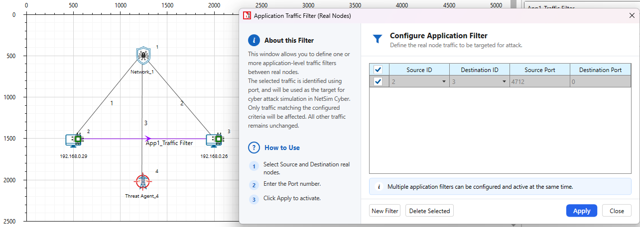
NetSim Cyber allows users to provide custom packet-modification logic through payload_modifier_custom.py. This file is intended for customer-defined attacks when the built-in protocol attackers do not cover the required behavior. NetSim calls the custom function for every packet that matches the Application Traffic Filter and passes through the configured Threat Agent.
Purpose
Use the custom payload modifier when a user needs to test protocol-specific logic, field replacement, byte-level corruption, or simple filtering behavior without developing a full built-in attacker UI. The custom script operates on the application-layer payload. The NetSim Application Traffic Filter should be used to select the required protocol or port before packets reach the custom modifier.
API Entry Point
The customer should implement attack logic inside the following function:
def modify_payload(ipv4, ipv6, tcp, udp, payload, iopath):
Function Parameters
| Parameter | Description | Common Fields / Use |
|---|---|---|
| ipv4 | Network-layer packet handle supplied by NetSim. It may be an internal NetSim object. | Usually ignored for simple payload-only attacks. |
| ipv6 | Network-layer packet handle supplied by NetSim. It may be an internal NetSim object. | Usually ignored for simple payload-only attacks. |
| tcp | Transport-layer packet handle supplied by NetSim. It may be an internal NetSim object. | Use the NetSim Application Traffic Filter to select TCP traffic. |
| udp | Transport-layer packet handle supplied by NetSim. It may be an internal NetSim object. | Use the NetSim Application Traffic Filter to select UDP traffic. |
| payload | Writable application-layer byte buffer. | Read using payload[offset], write using payload[offset] = value, check length using len(payload). |
| iopath | NetSim-provided simulation I/O path. | Use for logs, configuration files, temporary files, or external attack parameters. Simple payload-only attacks can ignore it. |
Required Return Rule
The function must return True when the payload is modified and False when the packet is not modified. If the payload is empty, read-only, or not selected for attack, return False.
Safe Editing Guidelines
Always check that payload is not None and len(payload) is sufficient before reading or writing an offset.
Use protocol documentation or Wireshark to identify the correct byte offset before modifying a field.
Use the NetSim Application Traffic Filter to select the target protocol or port before packets reach the custom modifier.
Use big-endian or little-endian packing based on the protocol field format.
Keep debug output limited and use the NetSim console only when troubleshooting.
Example Patterns
import struct
import sys
def modify_payload(ipv4, ipv6, tcp, udp, payload, iopath):
try:
if payload is None or len(payload) == 0:
return False
mv = memoryview(payload)
if mv.readonly:
return False
# Pattern 1: modify a single byte after confirming the offset exists.
# if len(mv) > OFFSET:
# mv[OFFSET] = NEW_BYTE_VALUE
# return True
# Pattern 2: increment or decrement a numeric byte safely.
# if len(mv) > OFFSET:
# mv[OFFSET] = (mv[OFFSET] + DELTA) & 0xFF
# return True
# Pattern 3: overwrite a two-byte field using the protocol byte order.
# if len(mv) >= OFFSET + 2:
# struct.pack_into(">H", mv, OFFSET, NEW_VALUE)
# return True
# Pattern 4: enable temporary debug logging while developing.
# print("Payload length:", len(payload), "IO path:", iopath, file=sys.stderr)
return False
except Exception as exc:
print(f"Custom payload modifier error: {exc}", file=sys.stderr)
return False
Where This Fits in the Workflow
In the NetSim Cyber GUI, the user selects Import Custom Attacker in the Select Attack Protocol window and browses to a compatible Python payload modifier. NetSim passes ipv4, ipv6, tcp, udp, payload, and iopath to the custom function. The custom modifier is then applied by the Threat Agent to the traffic selected by the Application Traffic Filter during simulation.
The screenshot below shows the Custom Attacker area used to import the Python payload modifier before running the simulation.
Select Attack Protocol window showing the Import Custom Attacker option and the imported payload_modifier_custom.py file.