Lab Setup and Network Configuration
This section describes how to set up NetSim Cyber for same-system and distributed cyber-attack simulation experiments. The purpose of the lab setup is to ensure that protocol traffic flows through the NetSim Cyber Threat Agent before reaching the destination application or device.
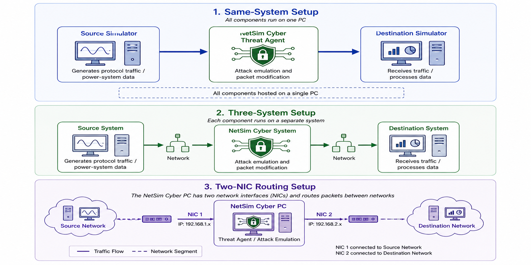
NetSim Cyber can be used in different network configurations depending on the experiment. For early-stage testing, all components may run on a single system. For realistic testing, the source, NetSim Cyber system, and destination may run on separate systems or devices.
The main lab setup options are:
Single-system setup
Three-system setup
Manual route configuration
Automatic configuration using NetSim Cyber Client
Two-NIC routing setup
| Setup Type | Description | Recommended Use |
|---|---|---|
| Same-system setup | Source simulator, NetSim Cyber, and destination simulator run on one PC | Training, quick testing, protocol validation |
| Three-system setup | Source, NetSim Cyber, and destination run on separate systems | Real-device testing, distributed lab setup |
| Manual route configuration | User manually configures routes through the NetSim Cyber system | Controlled routing and fixed IP environments |
| Automatic configuration | NetSimCyberClient.exe automatically detects NetSim Cyber and updates routes | Faster distributed setup |
| Two-NIC routing setup | NetSim Cyber PC routes traffic between two separate networks | HIL, RTDS, Typhoon HIL, and isolated subnet testing |
NetSim Cyber lab setup options
System Configuration Setup
Detailed Setup Configuration
Method 1: Manual Route Configuration
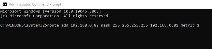
1. Source system (192.168.0.83)
To add a static route, you'll need to open the command prompt in administrator mode. Once open, input the following command:
route add <Destination IP address> mask <Subnet mask> <Gateway IP address> metric 1
Command Example:
route add 192.168.0.82 mask 255.255.255.255 192.168.0.81 metric 1
Example for configuring static route in source system
Replace <Destination IP address> with the IP address of the destination system, <Subnet mask> with the appropriate subnet mask, and <Gateway IP address> with the IP address of the gateway. This command will effectively add the static route.
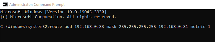
2. Destination system (192.168.0.82)
To facilitate communication for TCP traffic, it's essential to configure a reverse route on the destination system as well.
route add <IP address of Destination system> mask <Subnet mask> <Gateway IP address> metric 1
Command Example:
route add 192.168.0.83 mask 255.255.255.255 192.168.0.81 metric 1
Example for configuring static route in Destination system
Method 2: Automatic Configuration using NetSim Cyber Client
As an alternative to manually configuring routes on the source and destination systems, users can utilize the NetSimCyberClient.exe utility to automate the process.
Prerequisites: Before proceeding, ensure the NetSim Cyber Suite UI is running on the gateway system (192.168.0.81)
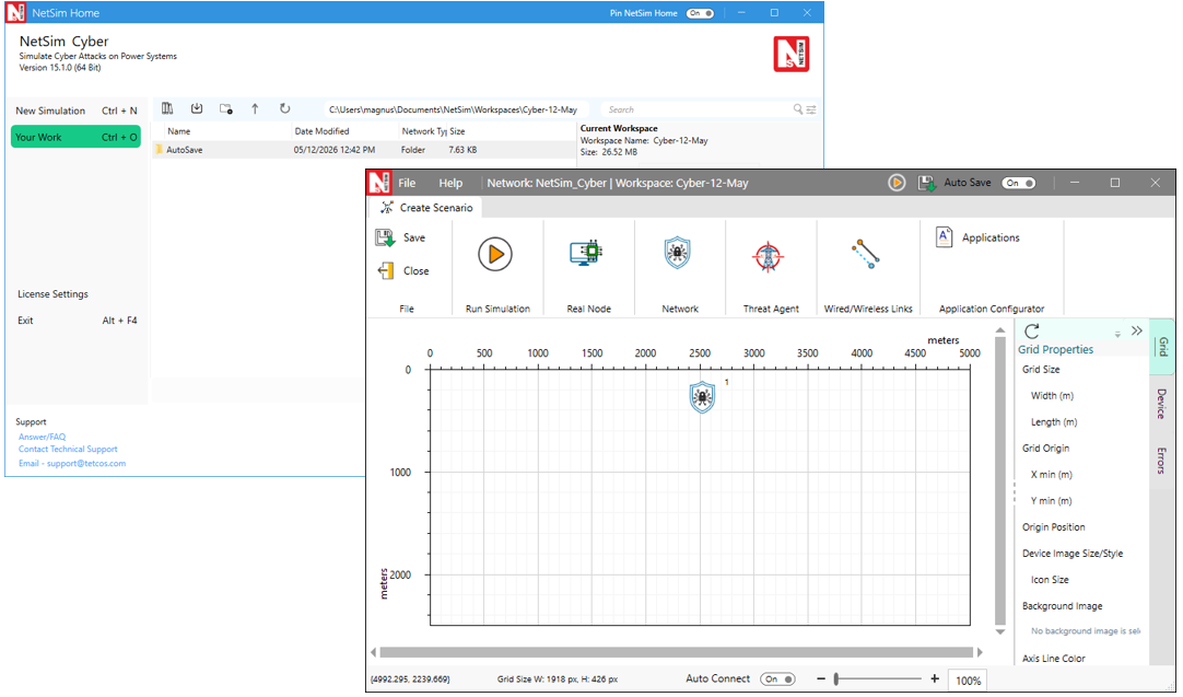
Launching the NetSim Cyber on the gateway system (IP: 192.168.0.81)
Steps:
Place the NetSimCyberClient.exe utility on both the Source/Client system (192.168.0.83) and the Destination/Server system (192.168.0.82).
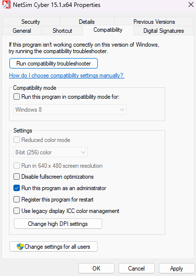
Run the NetSimCyberClient.exe as run as administrator on both systems.
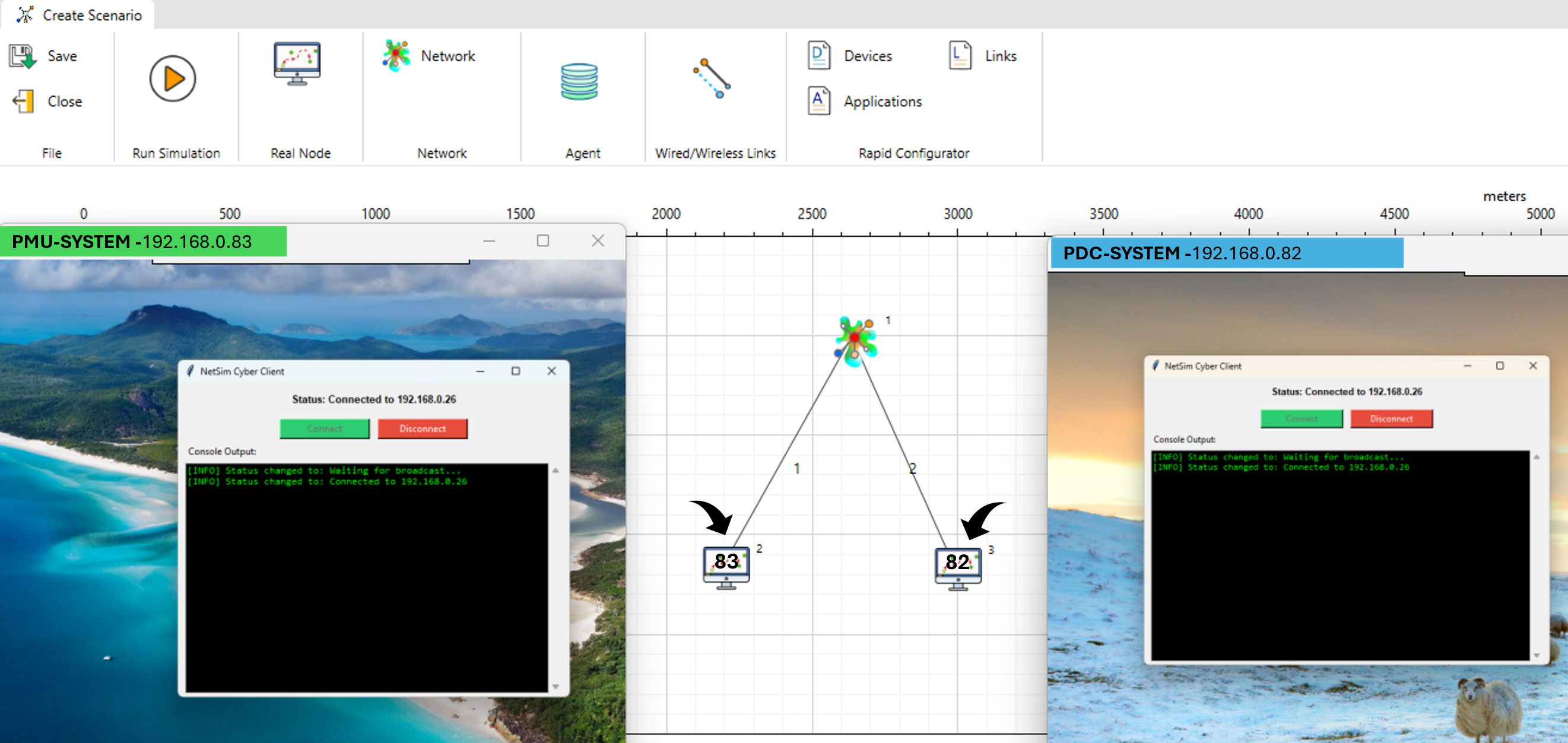
NetSimCyberClient.exe utility interface showing the Connect option and traffic tools, launched with administrator privileges on both source/destination systems
Upon running the utility, the nodes will automatically be dropped into the NetSim environment, as seen in the above example layout where distinct nodes connect to the central network cloud. The routing tables on the client and server systems will be updated automatically to direct traffic through the NetSim gateway.
How it works:
When the NetSim Cyber tile starts on the gateway system, it begins broadcasting a message containing its IP address across the entire network on port 19001 every second.
NetSimCyberClient utility runs on the client or server system, it starts listening for these broadcast messages on port 19001.
Upon receiving a message from the network on this port, the utility establishes a connection with the NetSim system.
It then automatically alters the local route table so that packets are transmitted through the system running NetSim.
Finally, it starts sending packets containing its own IP address and Device Name to NetSim. When NetSim receives these packets on port 19001, it reads the information and automatically drops a device node with the respective IP address and Device Name into the simulation scenario.
Troubleshooting Automatic Configuration
| Problem | Possible Cause | Recommended Action |
|---|---|---|
| Client does not detect NetSim Cyber | Discovery traffic blocked | Check firewall and network reachability |
| Client does not update routes | Client not run as Administrator | Relaunch NetSimCyberClient.exe as Administrator |
| Device does not appear in NetSim Cyber | Client not connected or wrong network | Check IP address and network adapter |
| Traffic bypasses NetSim Cyber | Route update failed | Run route print and verify gateway |
| Connection works but attack not applied | Application filter mismatch | Check source, destination, protocol, and port |
NetSim Cyber Client troubleshooting
Method-3: Three-System Network Configuration for NetSim Cyber
This document describes how to configure a three-system network setup for NetSim Cyber. The same procedure can be used with:
Typhoon HIL
RTDS systems (GTNET Card, PMU, PDC)
RTAC devices
Other Ethernet-based simulation or control systems
The setup uses a Windows PC running NetSim Cyber as a router between two separate networks.
Overview
The setup contains three systems:
Source-side device or simulator
Example: Typhoon HIL
Routing system
Windows PC with NetSim Cyber installed
Contains two Ethernet interfaces
Routes traffic between both networks
Destination-side device or simulator
Example: RTAC, PMU, or PDC
Example Network Topology
Three-System Network Configuration
Example IP Configuration
Source-Side Network:
| Parameter | Value |
|---|---|
| Device | Typhoon HIL |
| IP Address | 10.220.65.110 |
| Subnet Mask | 255.255.255.0 |
| Default Gateway | 10.220.65.1 |
Source-Side Network Configuration
NetSim Cyber PC
The NetSim Cyber system must contain two Ethernet interfaces.
Ethernet Interface Connected to Source Network:
| Parameter | Value |
|---|---|
| Interface | Ethernet 3 |
| IP Address | 10.220.65.1 |
| Subnet Mask | 255.255.255.0 |
Ethernet Interface Configuration for Source Network
Ethernet Interface Connected to Destination Network:
| Parameter | Value |
|---|---|
| Interface | Ethernet 2 |
| IP Address | 10.220.64.1 |
| Subnet Mask | 255.255.255.0 |
Ethernet Interface Configuration for Destination Network
Destination-Side Network:
| Parameter | Value |
|---|---|
| Device | RTAC |
| IP Address | 10.220.64.234 |
| Subnet Mask | 255.255.255.0 |
| Default Gateway | 10.220.64.1 |
Destination-Side Network Configuration
Requirements
Before starting the configuration, ensure the following requirements are met.
Hardware Requirements:
Three systems or devices connected through Ethernet
Two Ethernet ports available on the NetSim Cyber PC
Ethernet cables and network connectivity
Software Requirements:
Windows operating system on the NetSim Cyber PC
NetSim Cyber installed
Administrator access on the NetSim Cyber PC
Configure IP Address and Gateway
Perform the following steps on each system.
Step 1: Open Network Adapter Settings
Open: Control Panel
Navigate to: Network and Internet > Network and Sharing Centre
Click: Change adapter settings
Right-click the required Ethernet adapter.
Select: Properties
Step 2: Open IPv4 Settings
Select: Internet Protocol Version 4 (TCP/IPv4)
Click: Properties
Select: Use the following IP address
Step 3: Enter Network Settings
Enter the IP address, subnet mask, and default gateway based on the configuration tables shown earlier.
After entering the values:
Click: OK
Close all remaining windows.
Repeat the same procedure for all required systems and interfaces.
Enable IP Forwarding on the NetSim Cyber PC
The NetSim Cyber PC acts as a router between the two networks. IP forwarding must therefore be enabled.
Step 1: Open PowerShell as Administrator
Open the Windows Start menu.
Search for: PowerShell
Right-click Windows PowerShell.
Select: Run as administrator
Step 2: Enable Packet Forwarding
Execute the following command:
Set-NetIPInterface -Forwarding Enabled
What This Command Does?
This command enables packet forwarding on the network interfaces.
Without this setting, Windows will not route packets between the two Ethernet interfaces.
Step 3: Enable IP Routing in Windows
Execute the following command:
Set-ItemProperty -Path "HKLM:/SYSTEM/CurrentControlSet/Services/Tcpip/Parameters" -Name "IPEnableRouter" -Value 1
What This Command Does?
This command enables Windows IP routing through the registry.
It updates the following registry setting:
IPEnableRouter = 1
This allows the NetSim Cyber PC to function as a network router.
Step 4: Restart the System
Restart the NetSim Cyber PC after executing the PowerShell commands.
This ensures that the routing configuration is applied correctly.
Verification
After completing the configuration, verify that communication works correctly between both networks.
Verify IP Configuration
Open Command Prompt or PowerShell and execute:
ipconfig
Verify that:
All interfaces show the correct IP addresses
Subnet masks are correct
Gateways are configured properly
Verify Network Connectivity from the Source-Side System
Execute: ping 10.220.64.234
Expected Result
Successful replies confirm that the source-side system can reach the destination-side system through the NetSim Cyber PC.
From the Destination-Side System
Execute: ping 10.220.65.110
Expected Result
Successful replies confirm bidirectional communication between both networks.
Verify Interface Forwarding
On the NetSim Cyber PC, execute: Get-NetIPInterface
Verify that forwarding is enabled on the required Ethernet interfaces.
Verify NetSim Cyber Operation
Start traffic generation or communication between the connected systems and verify that:
Traffic passes between both networks
NetSim Cyber captures or processes the traffic correctly
Communication remains stable during operation
Connectivity Troubleshooting
| Problem | Likely Cause | Recommended Action |
|---|---|---|
| Source cannot ping destination | Incorrect IP, subnet, gateway, or cable connection | Verify ipconfig, cable, switch, and adapter settings |
| Destination cannot ping source | Reverse route missing | Add reverse route through NetSim Cyber |
| Ping works but protocol does not connect | Firewall or wrong port | Allow protocol port and verify application configuration |
| Traffic bypasses NetSim Cyber | Route not configured correctly | Run route print and update static routes |
| NetSim Cyber Client does not connect | Discovery blocked or client not run as Administrator | Check firewall and relaunch client as Administrator |
| Attack does not apply | Wrong traffic filter or protocol selection | Verify source, destination, protocol, and port |
| Two-NIC setup does not route traffic | IP forwarding not enabled | Enable forwarding and restart NetSim Cyber PC |
| Destination receives no data after attack starts | Payload corrupted or wrong attack selected | Stop attack, verify protocol selection, and retest baseline |
Connectivity troubleshooting
After completing the lab setup and connectivity verification, the NetSim Cyber environment is ready for attack configuration. Users should always verify baseline communication before enabling any attack. This ensures that any observed change at the destination is due to the configured Threat Agent behavior and not due to routing, firewall, or protocol setup errors.