About SDN#
The salient features of SDN are:
-
Directly programmable: SDN decouples the network control and forwarding functions. SDN allows programming the network control plane by abstracting the physical infrastructure.
-
Agile: Decoupling and abstracting network control from forwarding helps administrators dynamically adjust network-wide traffic flow to meet the changing needs in the networks.
-
Centrally managed: Network intelligence is centralized (logically) in software based SDN controllers that maintain a global view of the network, which appear to applications and policy engines as a single, logical switch.
-
Programmatically configured: SDN lets network managers configure, manage, secure, and optimize network resources very quickly via dynamic, automated SDN programs, which they can write easily and quickly, because the programs do not depend on proprietary software.
-
Open standards-based and vendor-neutral: Because SDN is implemented through open standards, SDN simplifies network design and operation because instructions are provided by SDN controllers instead of multiple, vendor-specific devices and protocols.
SDN in NetSim#
SDN is available in NetSim from version 11 onwards. NetSim 'simulates' OpenFlow protocol. OpenFlow is an open interface to remotely control the forwarding tables in network switches, routers, etc.
SDN Controller in NetSim#
An SDN controller is an application in SDN that manages flow control to enable intelligent networking. SDN controller can be used to control the packet forwarding of all Layer 3 devices in the network.
SDN controller lies between the network devices and the applications. Any communication between applications and devices must go through the controller.
NetSim has inbuilt controllers that 'simulate' SDN. An SDN controller in NetSim contains a Command Line Interface (CLI) to allow you to configure properties, such as, the IP forwarding table for different devices in the network.
NetSim also provides a platform whereby users can develop various kind of commands/interface compatible to any SDN enabled device.
In NetSim, any Layer 3 device can be configured as an SDN Controller. Multiple controllers can be configured in a network scenario. The following is a list of Layer 3 devices you can configure as an SDN controller:
-
Internetworks – Nodes (Wired, Wireless Node), L3 Switches, Routers
-
MANETs – Nodes (Wired, Wireless Node), Bridge Node (Wired, Wireless Node), Routers
-
WSN - Sensors and Sink Node
-
IOT - Sensors and Gateway (LowPAN Gateway), Nodes (Wired, Wireless Node), Routers
-
Cognitive Radio – CR CPE, Nodes (Wired, Wireless Node), Routers
-
LTE – UE, EPC, Nodes (Wired, Wireless Node), Routers
-
VANETs – Vehicle and RSU
-
5G mmWave – UE, EPC, Nodes (Wired, Wireless Node), Routers
NOTE: NetSim ‘simulates’ SDN protocol and cannot connect to real controllers such as Open Daylight.
CLI Commands for SDN in NetSim#
You can use the following commands when you simulate SDN in NetSim:
Simulation-specific – Pause, PauseAt, Continue, Stop, Exit, and Reconnect.
Route – route add, route print, and route delete.
Ping Command – ping (not supported on some network types, for example, Wireless Sensor Network)
ACL configuration – ACL Enable, ACL Disable, ACL Print, and aclconfig.
Notes: CLI commands in NetSim are NOT case-sensitive. To get detailed help about how to use CLI commands in NetSim, see Section 3.5 NetSim Interactive Simulation in User Manual.
Configuring SDN in NetSim#
SDN protocol parameters can be accessed and configured from the Application layer properties of the devices.
-
Open-flow protocol must be enabled in the devices which are > configured as SDN Controller or SDN clients.
-
SDN Controller device must have the SDN Controller option set to > True.
-
SDN Client devices must have the SDN Controller option set to False > along with the Controller Device Name set as the SDN Controller > Device Name.
-
TCP protocol must be enabled in the SDN Controller and client > devices.
-
Interactive Simulation option needs to be set to True in the Run > time interaction tab that is part of the Run Simulation window.
When SDN commands are executed during runtime either via console or via file input, commands and response are exchanged between the controller and clients using TCP
How to use CLI Commands for SDN#
Each device in NetSim has a console which can be accessed by right clicking on the device. Users can execute supported SDN commands on the console of the SDN controller node to configure other nodes in the network. Let us look at a few examples.
Example 1: To view the IP routing table of a node that is controlled by the SDN controller, use the following command syntax: \<DeviceName with Device_ID> route print.
For example, type Wired_Node_2 route print and press Enter.
The following image illustrates the output for the command.
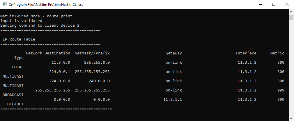
Figure ‑: Printing IP routing table in Console
Example 2: To initiate ping from one node to another node where both nodes are controlled by the SDN controller, following command can be executed in the SDN controller:
\<DeviceName with Device_ID> Ping \<DeviceName with Device_ID> or \<DeviceName with Device_ID> Ping \<IP Address>.
For example, type Router_4 ping Router_5 or Router_4 ping 11.1.1.2 and press Enter.
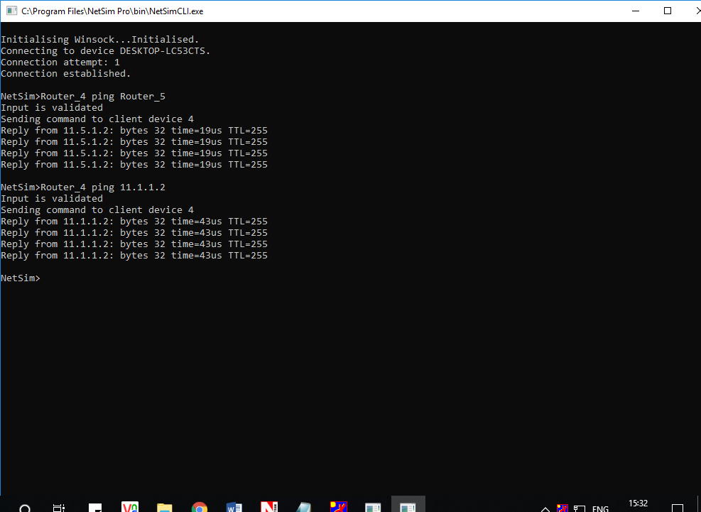
Figure ‑: Pinging Router_4
NOTE: In order to initiate ping between the devices, ICMP protocol which is present in the Network Layer properties of the devices must be set to TRUE.
Excluded Features#
Multiple controllers can be configured in NetSim. However, intercontroller communication requires the user to write their own code in NetSim.
Troubleshooting issues in executing SDN commands#
When executing SDN commands in the SDN controller, there can be cases where there is no response coming back. Some of the reasons for this are listed below:
-
SDN Controller and SDN client are unable to communicate (not > reachable).
-
Part of two different networks
-
Due to the distance between the devices in the case of wireless nodes
-
-
Failed TCP connection attempts due to high error or collision
-
Commands for Controller to the client and response from the client to the controller are passed as TCP packets.
-
The TCP connection attempt fails if the maximum connection attempt is reached.
-
-
High network traffic due to application packets exchanged during the > simulation
Some suggestions to resolve issues with SDN command execution are listed below:
-
Connectivity between the SDN controller and clients should be > ensured.
-
Application start time can be increased to allow necessary SDN > commands to be executed prior to application traffic flow which > will also avoid contention especially in the case of Wireless > devices.
-
SDN commands can be passed as input via file-based interactive > simulation for higher accuracy in terms of the time at which the > commands are to be executed.
Featured Examples#
NetSim provides inbuilt examples to get started with the SDN module. To access these examples, you can go to Examples > Software-Defined-Networks in the NetSim Home Screen. You can change the default values of the parameters in these examples and see how they affect the performance of the SDN network.
Configuring SDN#
Example 1: Configuring One SDN Controller in a Simple Internetwork #
The Internetwork model in this example consists of the following configuration:
-
A subnet with 2 wired nodes, 3 routers, and a unicast application running on one of the wired nodes.
-
Only one router is configured as the SDN controller.
-
Open Flow protocol is enabled on all wired nodes and routers.
-
A unicast application is set between Wired_Node_1 to Wired_Node_2.
-
Set Transport Protocol to TCP in Application icon present in the top ribbon/toolbar.
-
Simulation time is set to 500 seconds.
-
Plots, Packet trace, and Event trace logs are enabled.
To simulate the example for One SDN controller in an Internetwork:
Open NetSim and Select Examples > Software Defined Networks > Configuring SDN > SDN Internetworks then click on the tile in the middle panel to load the example as shown in below
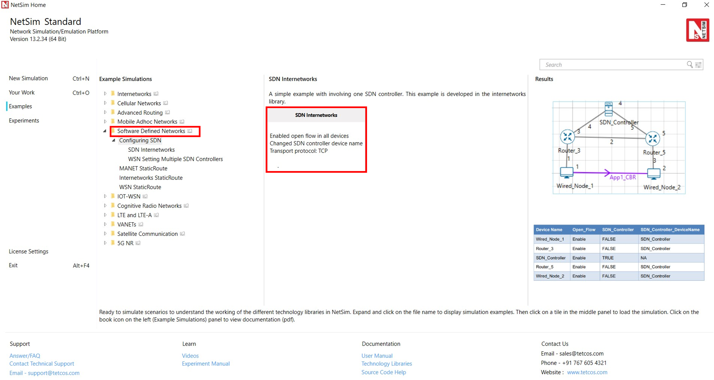
Figure ‑: List of scenarios for the example of SDN Internetworks
The following network diagram illustrates what the NetSim UI displays when you open the example configuration file for SDN as shown Figure 3‑2.
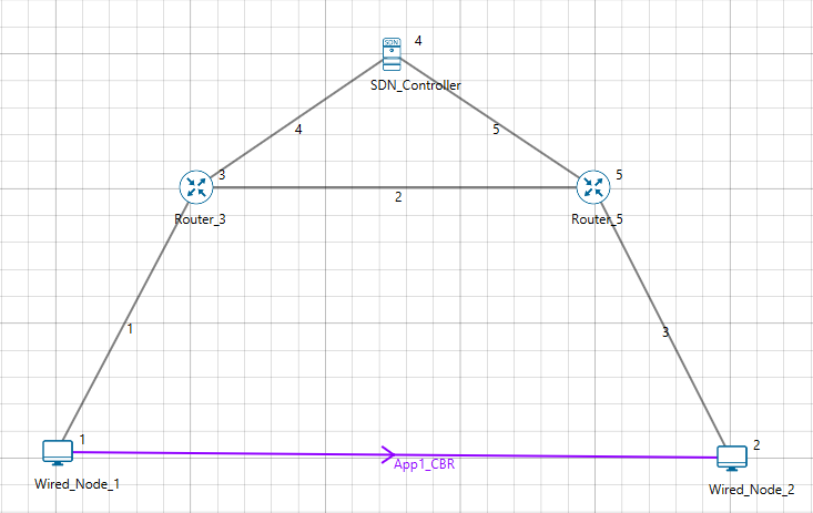
Figure ‑: Network set up for studying the SDN Internetworks
-
In the application layer of the SDN Controller node:
-
SDN_Controller option set to TRUE.
-
Open_Flow protocol is enabled.
The following image illustrates the settings done in the SDN controller device:
-
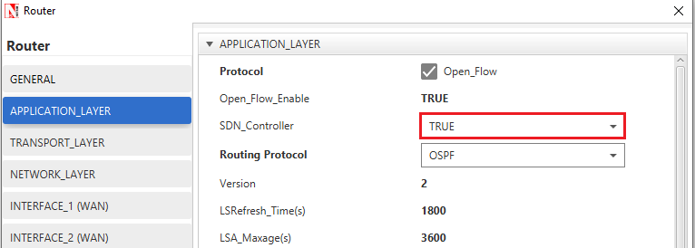 Figure ‑: Application Layer
properties Window of SDN_Controller device
Figure ‑: Application Layer
properties Window of SDN_Controller device
- In the other devices (Routers and wired node) that are part of the network,
-
-
SDN_Controller option is set to FALSE.
-
SDN_Controller_DeviceName is set as “SDN_Controller” > which is the name of the controller node.
-
Open_Flow protocol is enabled.
The following image illustrates settings done in the other devices:

-
Figure ‑: SDN_Controller_DeviceName is set as SDN_Controller in Application layer
The following table lists the settings done in all the devices that are part of the network:
| Device Name | Open_Flow | SDN_Controller | SDN_Controller_DeviceName |
|---|---|---|---|
| Wired_Node_1 | Enable | FALSE | SDN_Controller |
| Router_3 | Enable | FALSE | SDN_Controller |
| SDN_Controller | Enable | TRUE | NA |
| Router_5 | Enable | FALSE | SDN_Controller |
| Wired_Node_2 | Enable | FALSE | SDN_Controller |
Table ‑: Set the properties for all the devices
- Click on the Application icon present in the top ribbon/toolbar.
-
-
CBR Application from Wired Node 1 to Wired Node 2 with 50 Mbps > Generation Rate (Packet Size: 1460Bytes, Inter Arrival Time: > 233.6µs).
-
Set Transport Protocol to TCP.
-
- Simulate the example. To do so:
-
-
Click on the Run. The Run Simulation pop-up window appears.
-
Simulation time is set to 500 Seconds.
-
In the Run time Interaction tab, Interactive Simulation option > is set to True.
-
Click Accept.
-
Click OK.
-
Simulation (NetSimCore.exe) starts to run. NetSimCore.exe displays the following message: waiting for first client to connect.
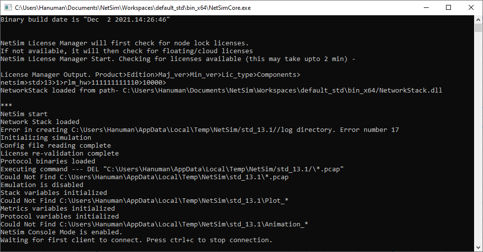
Figure ‑: Waiting for first client to connect
- To use the SDN CLI Console:
-
-
Right-click SDN_Controller and select NetSim Console. Now, > the client (NetSimCLI.exe) starts and attempts to establish a > connection with NetSimCore.exe.
-
The following image illustrates the NetSim CLI console.
-
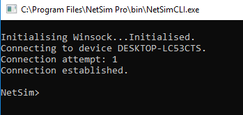
Figure ‑: Connection established
- Use this console to execute SDN commands.
Example 2: Configuring Multiple SDN Controllers in a Wireless Sensor Network #
In this example, multiple SDN controllers are configured in a Wireless Sensor Network.
The Wireless Sensor Network model in this example consists of the following configuration:
-
A subnet with 4 wireless sensors,1 ad-hoc link, 1 WSN sink node, and a unicast sensor application running on one of the wireless sensors.
-
Set Transport Protocol to TCP in Application icon present in the top ribbon/toolbar.
-
Two wireless sensors are configured as SDN controllers.
-
Open Flow protocol is enabled on all wireless sensors and sink node.
NetSim uses the following defaults for this SDN example:
-
-
The unicast application transmits data from Wireless Sensor_3 to Wireless Sensor_5.
-
Simulation runs for 500 seconds.
-
Plots, Packet trace, and Event trace is enabled.
-
NOTE: For a WSN network, ping command is not supported on ZigBee device since these nodes do not support ICMP protocol.
To simulate the example for multiple SDN controllers in WSN for SDN:
Open NetSim and Select Examples > Software Defined Networks > Configuring SDN > WSN Setting Multiple SDN Controllers then click on the tile in the middle panel to load the example as shown in below screenshot
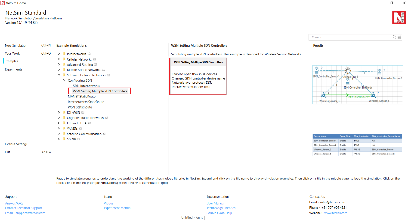
Figure ‑: List of scenarios for the example of WSN Setting Multiple SDN Controllers
The following network diagram illustrates the network setup related to this example as shown below Figure 3‑8.
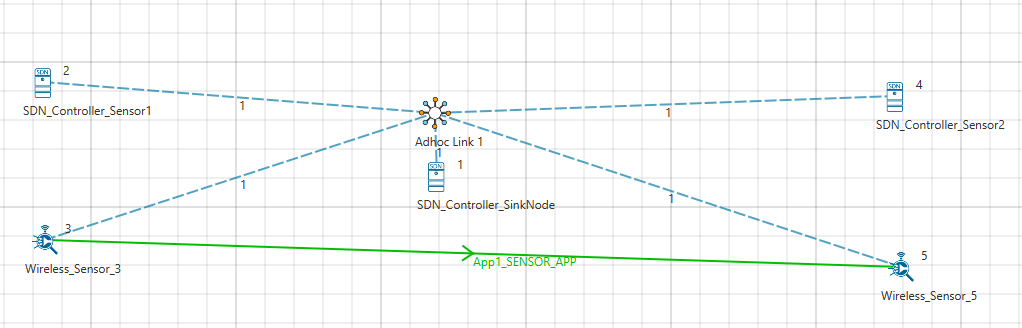
Figure ‑: Network set up for studying the WSN Setting Multiple SDN Controllers
- The sensors 1, 2 and the sinknode are configured as SDN controllers with Open Flow protocol enabled in all the nodes.
The following image illustrates the settings done in the sensors configured as SDN controller as shown below Figure 3‑9.

Figure ‑: Application Layer properties Window
- The sensor SDN_Controller_Sensor_1 is set as the SDN controller for Wireless_Sensor_3 and SDN_Controller_Sensor_2 is set as the SDN controller for Wireless_Sensor_5.
The following image illustrates the settings done in sensor 3 as shown Figure 3‑10.
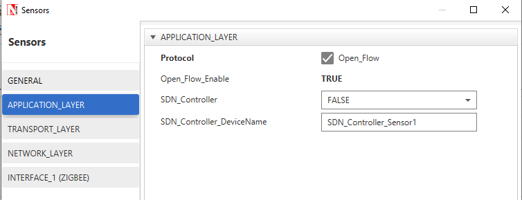
Figure ‑: SDN_Controller_DeviceName is set as SDN_Controller in Application layer
The following table lists the default setting for the wireless sensors.
| Device Name | Open_Flow | SDN_Controller | SDN_Controller_DeviceName |
|---|---|---|---|
| SDN_Controller_Sensor1 | Enable | TRUE | NA |
| SDN_Controller_Sensor2 | Enable | TRUE | NA |
| Wireless_Sensor_3 | Enable | FALSE | SDN_Controller_Sensor1 |
| Wireless_Sensor_5 | Enable | FALSE | SDN_Controller_Sensor2 |
Table ‑: Set the properties for all the devices
- Click on the Application icon present in the top ribbon/toolbar.
-
-
Sensor Application from Wireless_Sensor_3 to Wireless_Sensor_5 > with Packet Size: 50Bytes, Inter Arrival Time: 1000000µs).
-
Set Transport Protocol to TCP.
-
-
Additional analysis options such as plots, packet trace and event trace are enabled.
-
Simulate the example. To do so:
-
-
Click the Run button. The Run Simulation pop-up window appears.
-
Simulation time is set to 500 seconds.
-
In the Run time Interaction tab, Interactive Simulation option > is set to True.
-
Click Accept.
-
Click OK.
-
Simulation (NetSimCore.exe) starts to run. NetSimCore.exe displays the following message: waiting for first client to connect.
Figure ‑: Waiting for first client to connect
- To use the SDN CLI Console:
-
- Right-click SDN_Controller_Sensor1 or SDN_Controller_Sensor2 and > click NetSim Console.
Now, the client (NetSimCLI.exe) starts and tries to establish a connection with NetSimCore.exe.
The following image illustrates the NetSim CLI console.
Figure ‑: Connection established
You can execute various SDN commands that are supported.
Example 3: How to Change the IP tables in devices in NetSim using SDN Commands #
In the example the IP tables in the nodes and routers on an SDN network are modified using SDN CLI commands.
The network model in this example consists of the following configuration:
-
A subnet with 2 wired nodes, 5 routers, and a unicast application running on one of the wired nodes.
-
SDN controller running on one of the router.
-
Set Transport Protocol to TCP in Application icon present in the top ribbon/toolbar. Open Flow protocol is enabled on all wired nodes and routers.
-
A unicast application set from Wired_Node_1 to Wired_Node_2.
-
OSPF is the routing protocol in the routers.
-
The node SDN_Controller is configured to be the SDN controller.
-
Simulation time is set to 500 seconds.
-
Plots, Packet trace, and Event trace is enabled.
To simulate SDN and change the IP tables:
Open NetSim and Select Examples > Software Defined Networks > Internetworks StaticRoute then click on the tile in the middle panel to load the example as shown in below screenshot
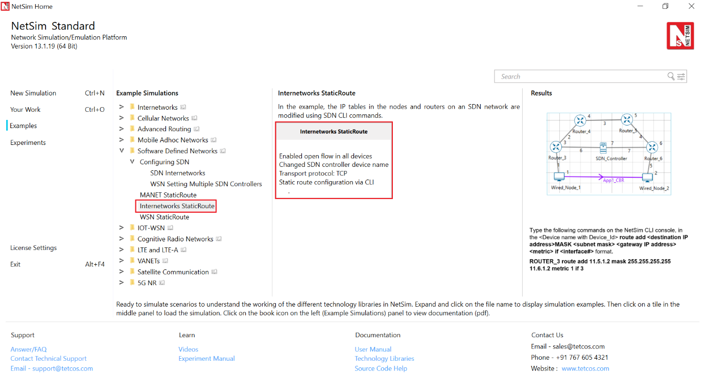
Figure ‑: List of scenarios for the example of Internetworks StaticRoute
The following network diagram illustrates the network setup related to this example as shown below Figure 3‑14.

Figure ‑: Network set up for studying the Internetworks StaticRoute
- Click on the Application icon present in the top ribbon/toolbar.
-
-
CBR Application from Wired Node 1 to Wired Node 2 with 50 Mbps > Generation Rate (Packet Size: 1460Bytes, Inter Arrival Time: > 233.6µs).
-
Application Start time is 30 sec.
-
Set Transport Protocol to TCP.
-
-
Plots, Packet Trace and Event Trace features are enabled.
-
Simulate SDN. To do so:
-
-
Click the Run button. The Run Simulation pop-up window appears.
-
Simulation time is set to 500 Seconds.
-
In the Run time Interaction tab, Interactive Simulation option > is set to True.
-
-
Right-click SDN_Controller and click NetSim Console. NetSim simulates SDN.
-
Interpret the results.
-
- Click View Animation and see the Packet Animation.
The packets reach Wired_Node_2 via Wired_Node_1 > Router 3 > SDN_Controller > Router 6 as shown in Figure 3‑15.

Figure ‑: Packet Animation window
-
-
Click View Results on the tool bar, Link metrics in the left area and check the Detailed View check box in the Link_Metrics_Table pop-up window. You will not see data packet transmissions in Links 2, 3, and 4 as shown in below Figure 3‑16.

-
Figure ‑: Link Metrics Table in result window
- Configure static routes on Router_3 such that all traffic bound for the 11.4.1.2 subnet will go to a gateway 11.2.1.2, that is, from Router_3 > Router_4 > Router_5 > Router_6.
To configure the static routes for Router_3:
-
-
Simulate the network again.
-
Now, right-click SDN_Controller and click NetSim Console.
-
Now, the client (NetSimCLI.exe) starts and attempts to establish > a connection with NetSimCore.exe. NetSim CLI console opens.
-
Type the following commands on the NetSim CLI console, in the > \<DeviceName with Device_ID> route add \<destination IP > address> MASK \<subnet mask> \<gateway IP address> > \<metric> if \<interface #> format. ROUTER_3 route > add 11.5.1.2 mask 255.255.255.255 11.2.1.2 metric 1 if 2
-
(Optional) To check the static routes on ROUTER_3, type > ROUTER_3 route print. The following image illustrates > step (c) and (d) as shown below Figure 3‑17.
-

Figure ‑: Route added to network and route printed in command
- Interpret the results.
-
-
Click View Animation and see the Packet Animation.
-
The packets reach Wired_Node_2 via Router 3 > Router_4 > > Router_5 > Router 6.
-
Click View Results on the tool bar, Link metrics in the > left area and check the Detailed View check box in the > Link_Metrics_Table pop-up window.
-
You will see data packet transmissions in Links 2, 3, and 4.
The following figure illustrates step (7c) as shown in below.
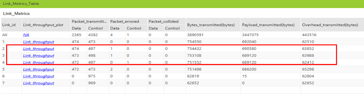
Figure ‑: Link Metrics Table
- In the simulation results window click on the Open Packet trace > option in the left area. Once the packet trace opens, apply > display filters to the
CONTROL_PACKET_TYPE/APP_NAME column to show only OPENFLOW_COMMAND and OPENFLOW_RESPONSE packets.
You will see that OpenFlow packets flow between Router_3 to SDN_Controller.
-
In Router_3 under appilication layer use routing protocol as RIP
-
Configure static routes for Router_3 as follows:
-
-
Simulate SDN (Refer step 4).
-
Right-click SDN_Controller and click NetSim Console.
-
Now, the client (NetSimCLI.exe) starts and tries to establish a connection with NetSimCore.exe. NetSim CLI console opens.
- Type the following commands on the NetSim CLI console, in the > \<DeviceName with Device_ID> route add \<destination IP > address> MASK \<subnet mask> \<gateway IP address> > \<metric> if \<interface #> format.
ROUTER_3 route add 11.5.1.2 mask 255.255.255.255 11.6.1.2 metric 1 if 3
- Interpret the results.
-
- Click View Animation and see the Packet Animation. The > packets reach Wired_Node_2 via Router 3 > SDN_Controller > > Router_6.
Example 4: Configuring Static Routes for a MANET Network by using SDN #
In this example static routes are configured using the SDN controllers, in a MANET network.
The MANET network model in this example consists of the following configuration:
-
A subnet with 5 wireless nodes and 1 ad-hoc link, and a unicast CBR application running on one of the wireless nodes.
-
DSR is the routing protocol that is enabled on all wireless nodes.
-
One wireless node is configured as the SDN controller.
-
Wireless nodes do not have mobility.
-
A unicast application is configured from Wireless_Node_1 to Wireless_Node_5.
-
Simulation time is set to 1000 seconds.
-
Packet trace, and Event trace is enabled.
To simulate the example for MANET using SDN:
Open NetSim and Select Examples > Software Defined Networks > MANET StaticRoute then click on the tile in the middle panel to load the example as shown in below screenshot
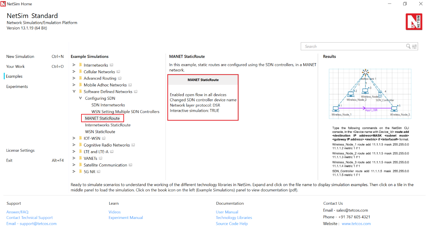
Figure ‑: List of scenarios for the example of MANET StaticRoute
The following network diagram illustrates the network setup as shown Figure 3‑20.
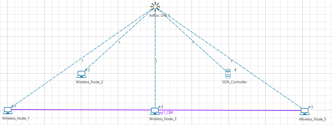
Figure ‑: Network set up for studying the MANET StaticRoute
- DSR routing protocol is configured in Network layer for all the nodes and set the nodes to be stationary.
-
Mobility model is set to NO_MOBILITY in all the nodes.
-
ICMP protocol is enabled in the network layer properties of all the wireless nodes.
-
Open flow protocol is enabled in all the wireless nodes.
The following settings were done in the wireless nodes to configure Wireless Node 4 as SDN controller and other nodes as its clients.
| Device Name | Open_Flow | SDN_Controller | SDN_Controller_DeviceName |
|---|---|---|---|
| Wireless_Node_1 | Enable | FALSE | SDN_Controller |
| Wireless_Node_2 | Enable | FALSE | SDN_Controller |
| Wireless_Node_3 | Enable | FALSE | SDN_Controller |
| SDN_Controller | Enable | TRUE | FALSE |
| Wireless_Node_5 | Enable | FALSE | SDN_Controller |
Table ‑: Set the properties for all the devices
- Click on the Application icon present in the top ribbon/toolbar.
-
-
CBR Application from Wireless_Node_1 to Wireless_Node_5 with 0.584 Mbps Generation Rate (Packet Size: 1460Bytes, Inter Arrival Time: 20000µs).
-
Set Transport Protocol to UDP.
-
-
Channel Characteristics: Path Loss Only, Path Loss Model: Log Distance, Path Loss Exponent:3.2.
-
In NetSim GUI Plots, Packet Trace and Event Trace are enabled.
-
Simulate the example. To do so:
-
-
Click the Run button. The Run Simulation pop-up window appears.
-
Simulation time is set to 1000 seconds.
-
In the Run time Interaction tab, the Interactive Simulation option is set to True.
-
Click Accept.
-
Click OK.
-
Simulation (NetSimCore.exe) starts to run. NetSimCore.exe displays the following message: waiting for first client to connect.
- To use the SDN CLI Console:
-
- Right-click SDN_Controller and select NetSim Console. Now, the client (NetSimCLI.exe) starts and attempts to establish a connection with NetSimCore.exe.
- Interpret the results.
-
- Click View Animation and see the Packet Animation.
The packets reach Wireless_Node_5 from Wireless_Node_1-> SDN_Controller -> Wireless_Node_5.
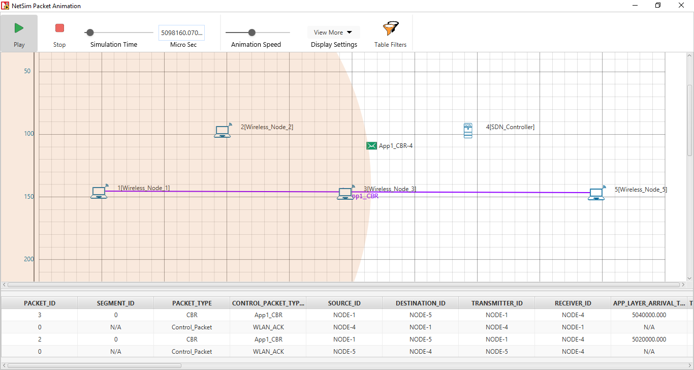
Figure ‑ : Packet Animation window
- Configure static routes such that the packets will go through Wireless_Node_1 > Wireless_Node_2, Wireless_Node_3, SDN_Controller to Wireless_Node_5.
To configure the static routes on SDN_Controller for all the nodes.
-
-
Run the simulation again.
-
Right-click SDN_Controller and select NetSim Console.
-
Now, the client (NetSimCLI.exe) starts and tries to establish a connection with NetSimCore.exe.
NetSim CLI console opens.
- Type the following commands on the NetSim CLI console, in the > \<DeviceName with Device_ID> route add \<destination IP > address> MASK \<subnet mask> \<gateway IP address> > \<metric> if \<interface #> format.
Wireless_Node_1 route add 11.1.1.5 mask 255.255.0.0 11.1.1.2 metric 1 if 1
Wireless_Node_2 route add 11.1.1.5 mask 255.255.0.0 11.1.1.3 metric 1 if 1
Wireless_Node_3 route add 11.1.1.5 mask 255.255.0.0 11.1.1.4 metric 1 if 1
SDN_Controller route add 11.1.1.5 mask 255.255.0.0 11.1.1.5 metric 1 if 1
- Interpret the results.
-
-
Click View Animation and see the Packet Animation. The > packets reach Wireless_Node_5 via Wireless_Node_1 > > Wireless_Node_2 > Wireless_Node_3 > SDN_Controller > > Wireless_Node_5.
-
In the simulation results window select the Open Packet > trace option in the left area. Once the packet trace opens > apply filter in the CONTROL_PACKET_TYPE/APP_NAME column to > show only OPENFLOW_COMMAND and OPENFLOW_RESPONSE > messages.
-
You will see that OpenFlow packets flow from Wireless_Node_1 > Wireless_Node_2 > Wireless_Node_3 > SDN Controller to Wireless_Node_5 as part of the commands executed for static route configuration.
Example 5: Configuring Static Routes for a WSN Network by using SDN #
In this example static routes are configured in sensors using SDN commands executed in a SDN controller.
The WSN network model in this example consists of the following configuration:
-
A subnet with 5 wireless sensor, 1 ad-hoc link, 1 wireless sink node, and a unicast sensor application running on one of the wireless sensors.
-
One wireless Sensor is configured as the SDN controller.
-
A unicast application from Wireless_Sensor_1 to Wireless_Sensor_5.
-
Simulation time of 500 seconds.
-
Packet trace is enabled.
To simulate the example for WSN using SDN:
Open NetSim and Select Examples > Software Defined Networks > WSN StaticRoute then click on the tile in the middle panel to load the example as shown in below screenshot

Figure ‑: List of scenarios for the example of WSN StaticRoute
The following network diagram illustrates the network setup considered in this example:

Figure ‑: Network set up for studying the WSN StaticRoute
- The following settings are done in the application layer properties of the devices for configuring SDN:
| Device Name | Open_Flow | SDN_Controller | SDN_Controller_DeviceName |
|---|---|---|---|
| Wireless_Sensor_1 | Enable | FALSE | SDN_Controller |
| Wireless_Sensor_2 | Enable | FALSE | SDN_Controller |
| SDN_Controller | Enable | TRUE | NA |
| Wireless_Sensor_4 | Enable | FALSE | SDN_Controller |
| Wireless_Sensor_5 | Enable | FALSE | SDN_Controller |
| WSN_Sink_6 | Enable | FALSE | SDN_Controller |
Table ‑: Set the properties for all the devices
- Click on the Application icon present in the top ribbon/toolbar.
-
-
Sensor Application from Wireless_Sensor_1 to Wireless_Sensor_5 > with default Generation Rate (Packet Size: 50Bytes, Inter > Arrival Time: 1000000µs).
-
Set Transport Protocol to UDP.
-
-
In NetSim GUI Plots and Packet Trace are enabled.
-
Simulate the example. To do so:
-
-
Click on the Run button. The Run Simulation pop-up window > appears.
-
Simulation time is set to 500 seconds.
-
In the Run time Interaction tab, the Interactive Simulation > option is set to True.
-
Click Accept.
-
Click OK.
-
Simulation (NetSimCore.exe) starts to run. NetSimCore.exe displays the following message: waiting for first client to connect.
- To use the SDN CLI Console:
-
- Right-click SDN_Controller and click NetSim Console. Now, > the client (NetSimCLI.exe) starts and attempts to establish a > connection with NetSimCore.exe.
- Interpret the results.
-
- Click View Animation and see the Packet Animation.
The packets reach Wireless_Sensor_5 from Wireless_Sensor_1 > SDN_Controller > Wireless_Sensor_5.

Figure ‑: Direct communication between node 1 and node 5 in packet Animation window
- Configure static routes such that the packets will go through Wireless_Sensor_1 to Wireless_Sensor_5 via SDN_Controller.
To configure the static routes on SDN_Controller for Wireless_Sensor_1
-
-
Run simulation again.
-
Right-click SDN_Controller and click NetSim Console.
-
Now, the client (NetSimCLI.exe) starts and tries to establish a connection with NetSimCore.exe and NetSim CLI console opens.
- Type the following commands on the NetSim CLI console, in the > \<DeviceName with Device_ID> route add \<destination IP > address> MASK \<subnet mask> \<gateway IP address> > \<metric> if \<interface #> format.
Wireless_Sensor_1 route ADD 11.1.0.0 MASK 255.255.0.0 11.1.1.4 METRIC 1 IF 1
SDN_Controller route ADD 11.1.0.0 MASK 255.255.0.0 11.1.1.6 METRIC 1 IF 1
- Interpret the results.
-
- Click View Animation and see the Packet Animation.
The packets reach Wireless_Sensor_5 from Wireless_Sensor_4 > SDN_Controller to Wireless_Sensor_5.
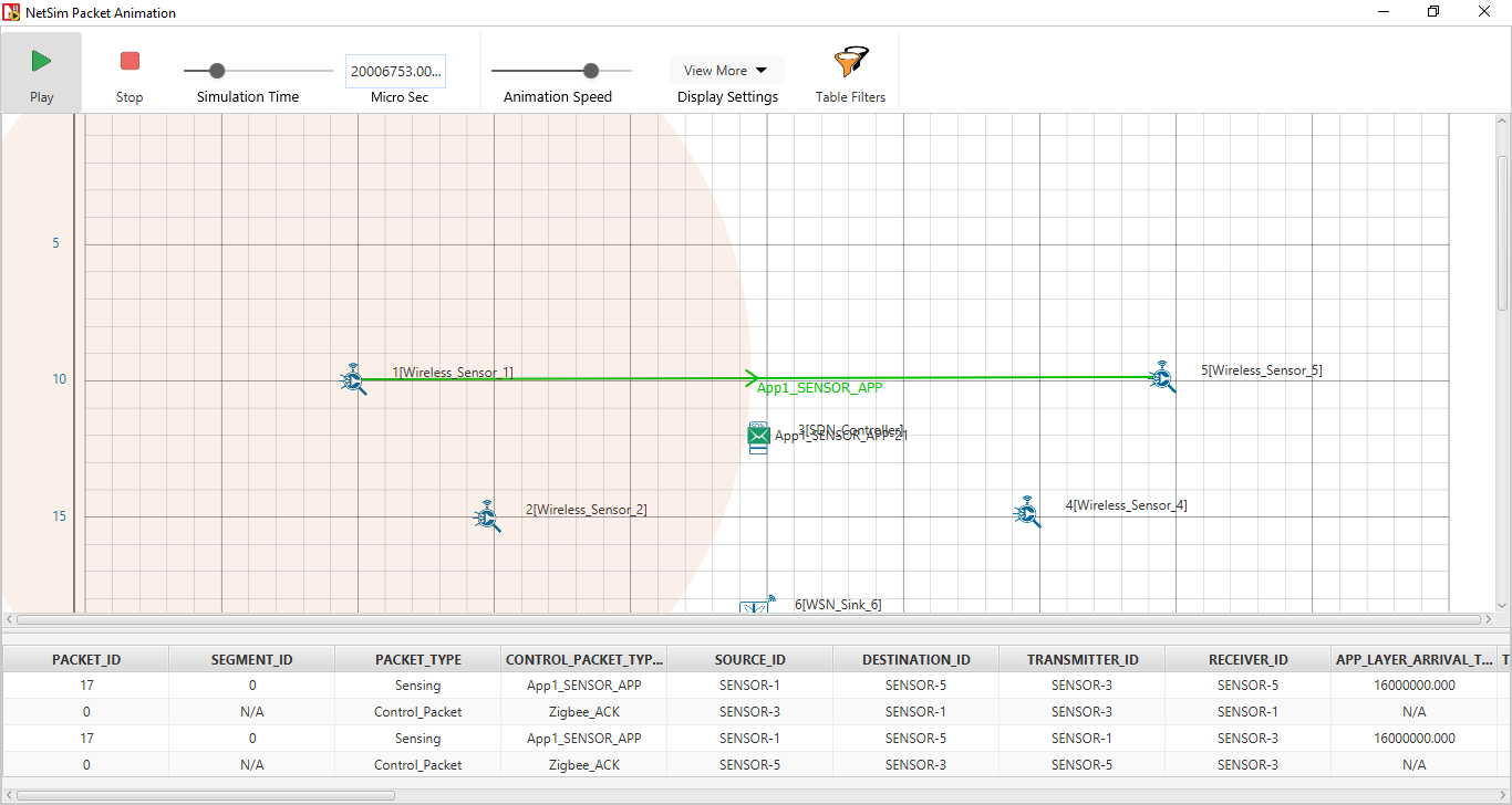
Figure ‑: Communication between node 1 > SDN Controller > node 5 in packet Animation window
- In the simulation results window select the Open Packet trace > option in the left area. Once the packet trace opens apply filter > in the CONTROL_PACKET_TYPE/APP_NAME column to show only > OPENFLOW_COMMAND and OPENFLOW_RESPONSE messages.
You will see that OpenFlow packets flow from Wireless_Sensor_4 to SDN_Controller as part of the static route configuration done via console.
Latest FAQs#
You can refer to the up-to-date FAQs about NetSim’s SDN library at
https://tetcos.freshdesk.com/support/solutions/folders/14000122307.