Featured Examples
Bandwidth variation through MCS configuration
Open NetSim, Select Examples ->Satellite Communication -> Bandwidth variation through MCS configuration then click on the tile in the middle panel to load the example as shown in Figure-1.
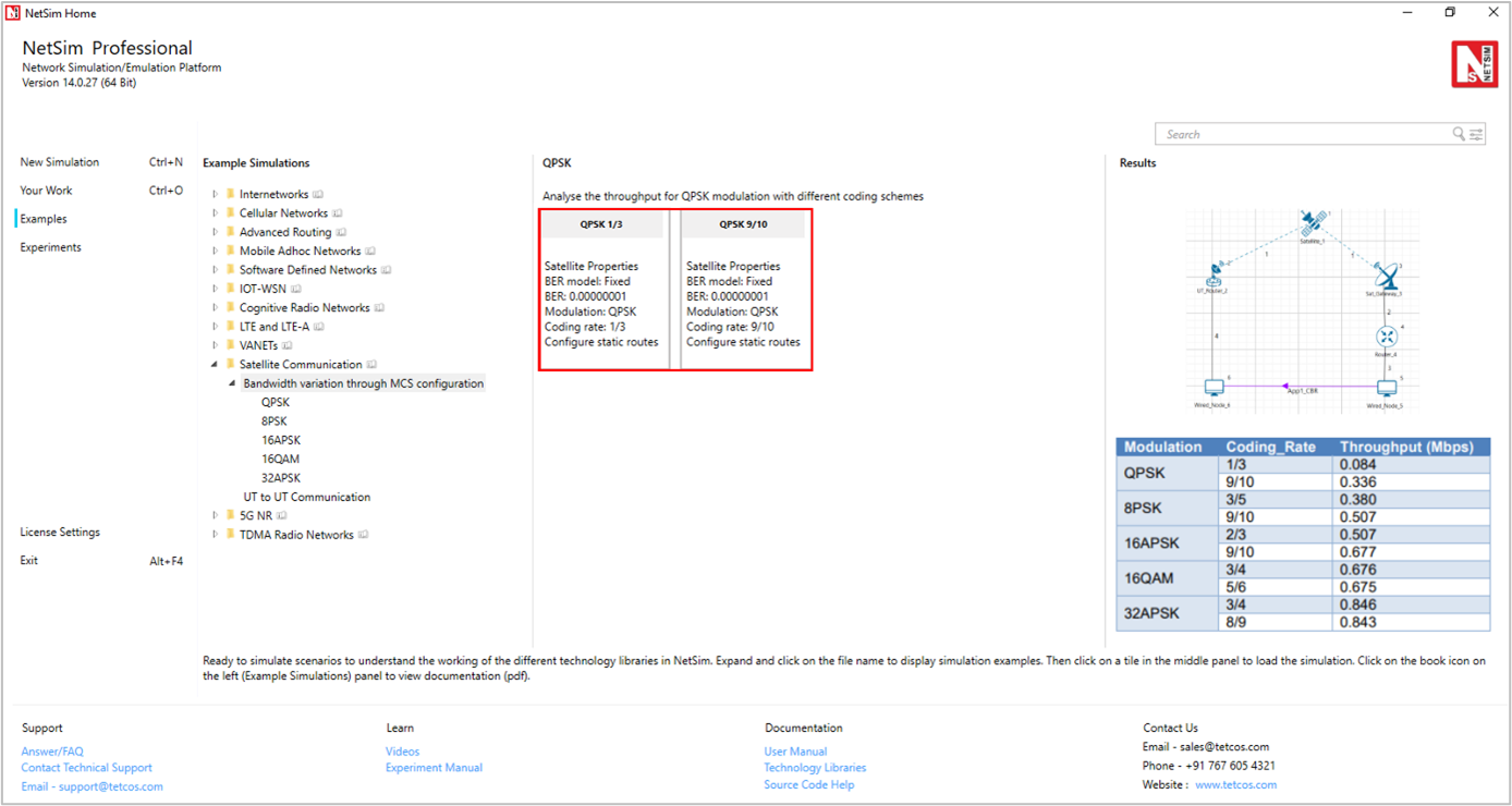
Figure-1: List of scenarios for the example of Bandwidth variation through MCS configuration
The following network diagram illustrates, what the NetSim UI displays when you open the example configuration file as shown Figure-2.
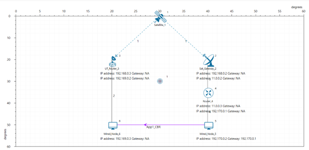
Figure-2: Network set up for studying the Bandwidth variation through MCS configuration.
Settings done in example config file:
Set the following property as shown in the table below. To configure it, click on the satellite device, expand the property panel on the right side, and change the property as below.
Satellite Properties -> Interface (Satellite) -> Physical Layer-> Forward |
|
|---|---|
BER Model |
Fixed |
BER |
0.00000001 |
Table-1: Satellite Properties > Interface (Satellite) > Physical Layer > Forward
Click on UT Router and set the following property as shown in below given table.
UT Router Properties -> Interface (Satellite) -> Datalink Layer |
|
|---|---|
Gateway |
Sat Gateway 2 |
Table-2: UT Router Properties > Interface (Satellite) > Datalink Layer
Note: For manually configured scenario, user need to mention the gateway name for UT nodes under datalink layer.
Go to Router 4 properties -> Network Layer ->Enable - Static IP Route ->Click on Static Route IP via GUI.
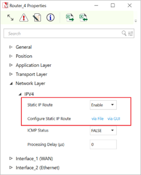
Figure-3: Router Network layer properties window
Set the properties in Static Route IP window as per the screenshot below and click on Add. Click on OK.
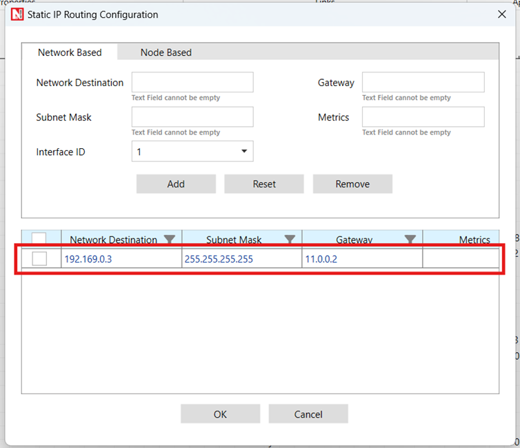
Figure-4: Configuring Static route window for router
Go to Sat Gateway 2 properties -> Network Layer ->Enable - Static IP Route ->Configure Static Route IP via GUI. Set the properties in Static Route IP window as per the screenshot below and click on Add. Click on OK.
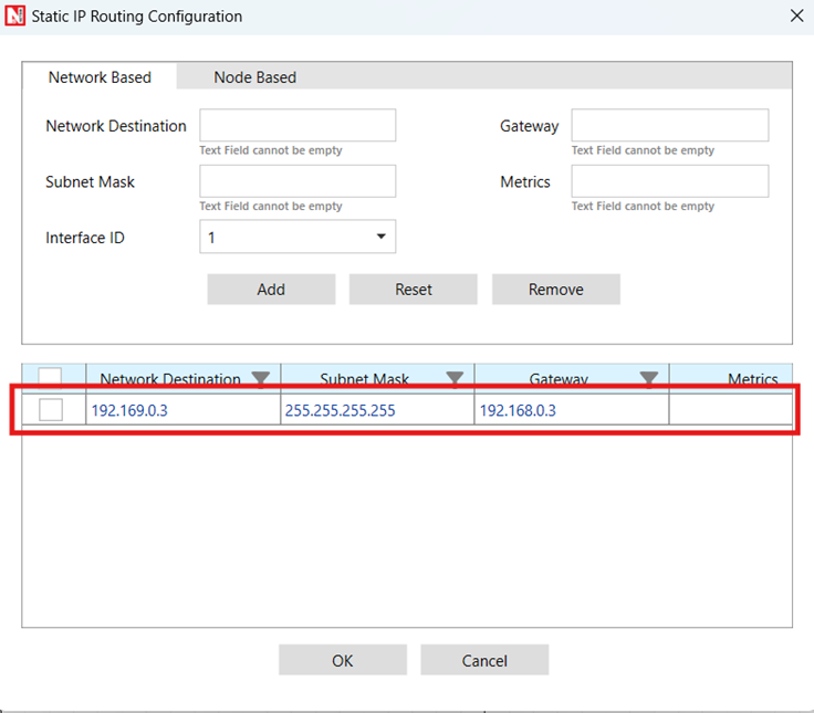
Figure-5: Configuring Static route window for Sat_Gateway_3
Go to UT Router 3 properties -> Network Layer -> Enable - Static IP Route -> Configure Static Route IP via GUI. Set the properties in Static Route IP window as per the screenshot below and click on Add. Click on OK.
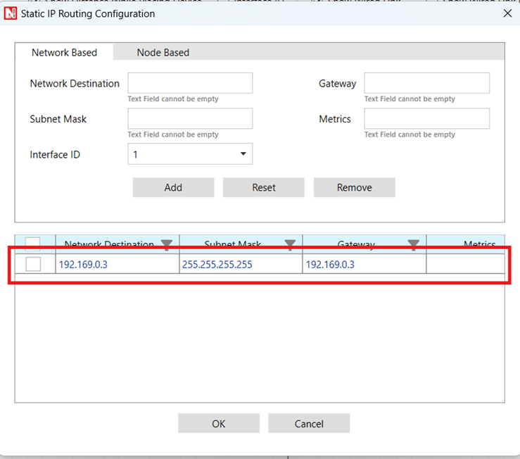
Figure-6: Configuring Static route window for UT_Router_2
Create a CBR application from set traffic tab in ribbon on the top between source id 5 to destination id 6 with packet size as 1460Bytes and Inter Arrival time as 467μs (Generation Rate=25Mbps). Transport Protocol is set to UDP.
Change the Satellite Properties 🡪 Interface (Satellite) 🡪 Physical Layer 🡪 Forward 🡪 Modulation and respective coding rates as shown in below Table-3 but for return link is fixed Modulation-> 32APSK and Coding Rate ->3/4.
Run simulation for 10 seconds and observe the result.
Note: Satellite properties in the physical layer changes done only for the forward and Return layer properties.
Result: Observe the application throughput as we change the modulation scheme (Satellite Properties 🡪 Interface (Satellite) 🡪 Physical Layer 🡪 Forward 🡪 Modulation) and respective coding rates (Satellite Properties 🡪 Interface (Satellite) 🡪 Physical Layer 🡪 Forward 🡪 Coding Rate).
Modulation |
Coding Rate |
Throughput (Mbps) |
|---|---|---|
QPSK |
1/3 |
0.084 |
9/10 |
0.336 |
|
8PSK |
3/5 |
0.379 |
9/10 |
0.504 |
|
16APSK |
2/3 |
0.505 |
9/10 |
0.675 |
|
16QAM |
3/4 |
0.677 |
5/6 |
0.677 |
|
32APSK |
3/4 |
0.844 |
8/9 |
0.846 |
Table-3: Compare the different Modulation Scheme and Coding Rate vs. Throughput.
Configuring applications from UT Node to UT Node
Open NetSim, Select Examples ->Satellite Communication -> UT to UT Communication then click on the tile in the middle panel to load the example as shown in below screenshot
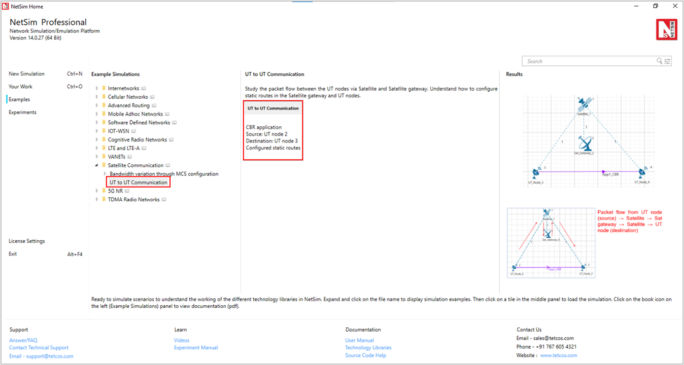
Figure-7: List of scenarios for the example of UT to UT Communication
The following network diagram illustrates, what the NetSim UI displays when you open the example configuration file as shown Figure-8.
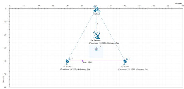
Figure-8: Network set up for studying the UT-to-UT Communication
Settings done in example config file
Click on UT node and expand the property panel on the right side and set the following property as shown in below given table:
UT Node Properties -> Interface (Satellite) -> DataLink Layer |
|
|---|---|
Gateway |
Sat Gateway 2 |
Table-4: UT Node Properties > Interface (Satellite) > DataLink Layer
Similarly, go to UT Node 3 properties -> Network Layer -> Enable - Static IP Route ->Configure Static Route IP.
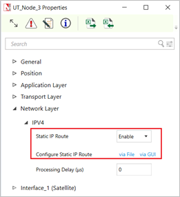
Figure-9: Network layer properties window for UT Node 3
Set the properties in Static Route IP window as per the screenshot below and click on Add. Click on OK.
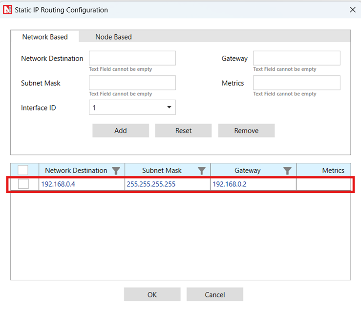
Figure-10: Configure static route for UT Node 2
Go to Sat Gateway 2 properties -> Network Layer -> Enable - Static IP Route ->Configure Static Route IP via GUI.
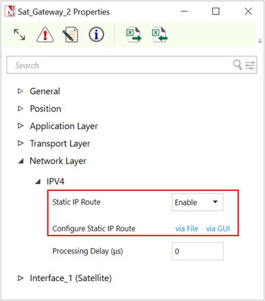
Figure-11: Network layer properties window for Sat Gateway 2
Set the properties in Static Route IP window as per the screenshot below and click on Add. Click on OK.
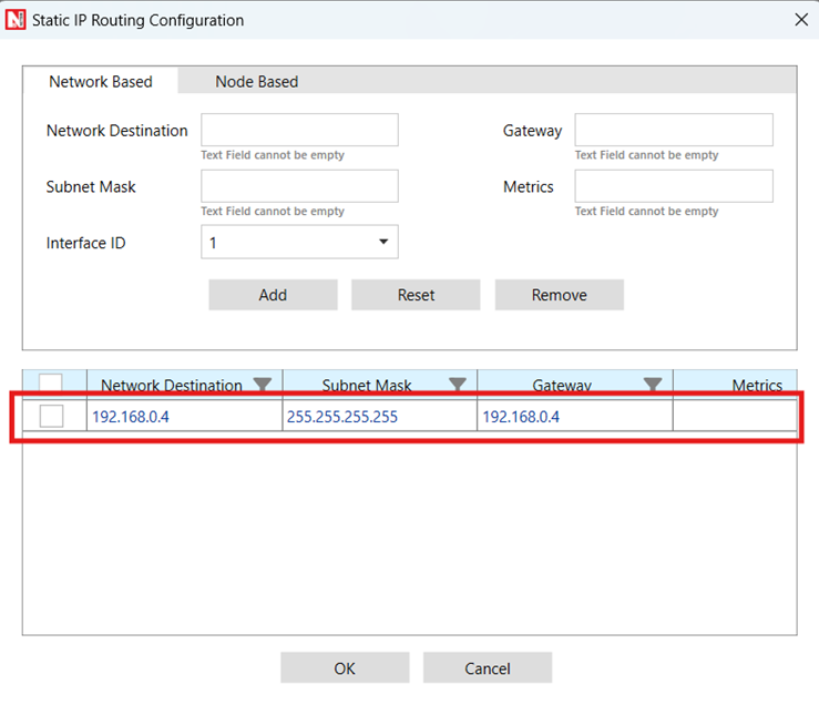
Figure-12: Configure static route for Satellite Gateway 2
Create application from set traffic tab in the ribbon on the top and set application properties as default (Packet Size: 1460, Inter Arrival Time: 20000 µs)
Click on application and set Transport Protocol to UDP in property panel.
Enable Packet Trace and Plots from the configure report tab.
Run simulation for 100 seconds and observe the result.
Result: Go to the result window and open packet trace, filter the PACKET_ID to 1. There, the user can observe the packet flow from UT node (source) 🡪 Satellite 🡪 Sat gateway 🡪 Satellite 🡪 UT node (destination)

Figure-13: Packet Trace.
Reference Documents
ETSI, "Digital Video Broadcasting (DVB); Second generation DVB interactive satellite system (DVB-RCS2); Part 2: Lower layers for satellite standard," ETSI EN 301 545-2 V1.2.1, Apr. 2014.
ETSI, "Digital Video Broadcasting (DVB); Second generation framing structure, channel coding and modulation systems for broadcasting, interactive services, news gathering and other broadband satellite applications (DVB-S2)," ETSI EN 302 307 V1.2.1, Aug. 2009.
Lu, D. Guo, A. Liu, and M. Yang, "Analysis of channel model for GEO satellite mobile communication system," in Proc. Nat. Conf. Inf. Technol. Comput. Sci. (CITCS), 2012.
Loo, "A statistical model for a land mobile satellite link," IEEE Trans. Veh. Technol., vol. 34, no. 3, pp. 122–127, Aug. 1985.