NetSim Cyber examples
Worked examples · NetSim Cyber 15.1
Four end-to-end examples of NetSim Cyber on live power-system traffic. In each example, a Threat Agent is in the communication path. In three examples, the Threat Agent changes the traffic. In the fourth, it inspects the traffic and drops packets that fall outside a defense profile. Each section gives the setup, the steps and the measured result.
The examples
Select an example to go to its section.
What all the examples have
All four examples use the same three parts. The sections below give only the data that is different for each example.
Traffic path
The source and the destination are Real Nodes in the NetSim Cyber scenario. A Threat Agent is between them. The Application Traffic Filter selects the flow by source, destination and port.
Attack or filter
A built-in protocol attacker (Synchrophasor or Modbus) or a Python Packet Modifier script operates on each selected packet. The script can modify the payload, drop the packet, or add delay.
Captures
NetSim Cyber writes four captures: PRE.pcap (source traffic),
MOD.pcap (modified), POST.pcap (forwarded) and
DROP.pcap (dropped). The destination shows the effect.
C37.118 synchrophasor attacks
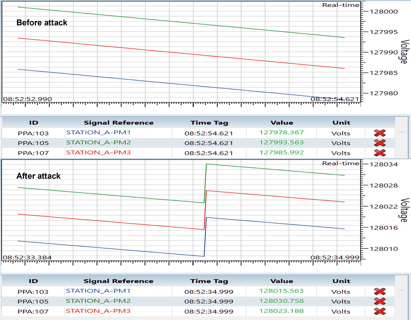
The Threat Agent changes a live IEEE C37.118-2005 stream between the PMU simulator and the PDC Manager. The PDC shows the effect of each attack, and the stream stays connected. The 2011 profile operates in the same procedure with the 2011 simulators and attacker profile.
Setup
- Profile
- IEEE C37.118-2005
- Source
- PMU simulator, TCP port 4712
- Destination
- PDC Manager
- Hosts
- Three systems: PMU source, NetSim Cyber host, PDC destination.
NetSimCyberClient.exeon the two endpoints sends the traffic through NetSim Cyber. Static routing is an alternative. - Attacker
- Built-in Synchrophasor attacker, 2005 profile
Steps
- Put the Threat Agent between the PMU and PDC Real Nodes.
- Set the Application Traffic Filter to the PMU source, the PDC destination and the TCP port.
- Select the Synchrophasor attacker with the 2005 profile. Start the simulation.
- Start the PMU, then connect the PDC Manager. The attacker reads the stream layout and phasor list from the first configuration frame.
- Apply an automatic attack or a manual injection. Monitor the PDC.
Start sequence
Start NetSim Cyber and the attacker before PMU traffic starts. If the PMU and the PDC complete their handshake first, the attacker does not see the configuration frame. Then the phasor list possibly does not load.
Attack modes shown
| Mode | Effect at the PDC |
|---|---|
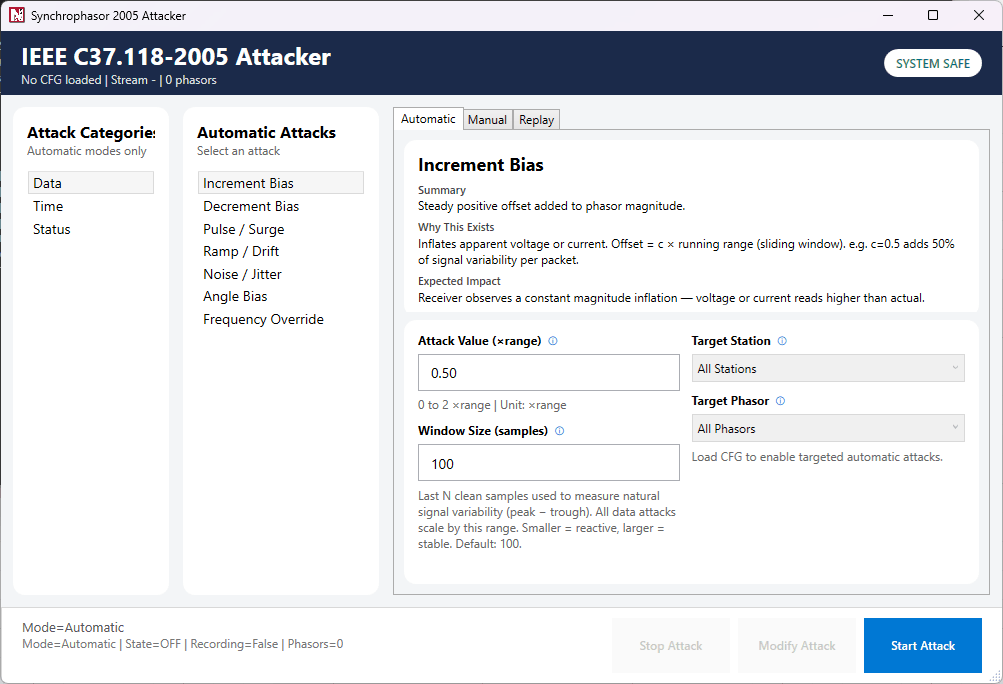
| Increment bias | Selected phasor magnitudes increase by an offset. |
| Decrement bias | Selected phasor magnitudes decrease by an offset. |
| Ramp / drift | Selected magnitudes change slowly, as with sensor drift. |
| Noise / jitter | Selected magnitudes change at random. |
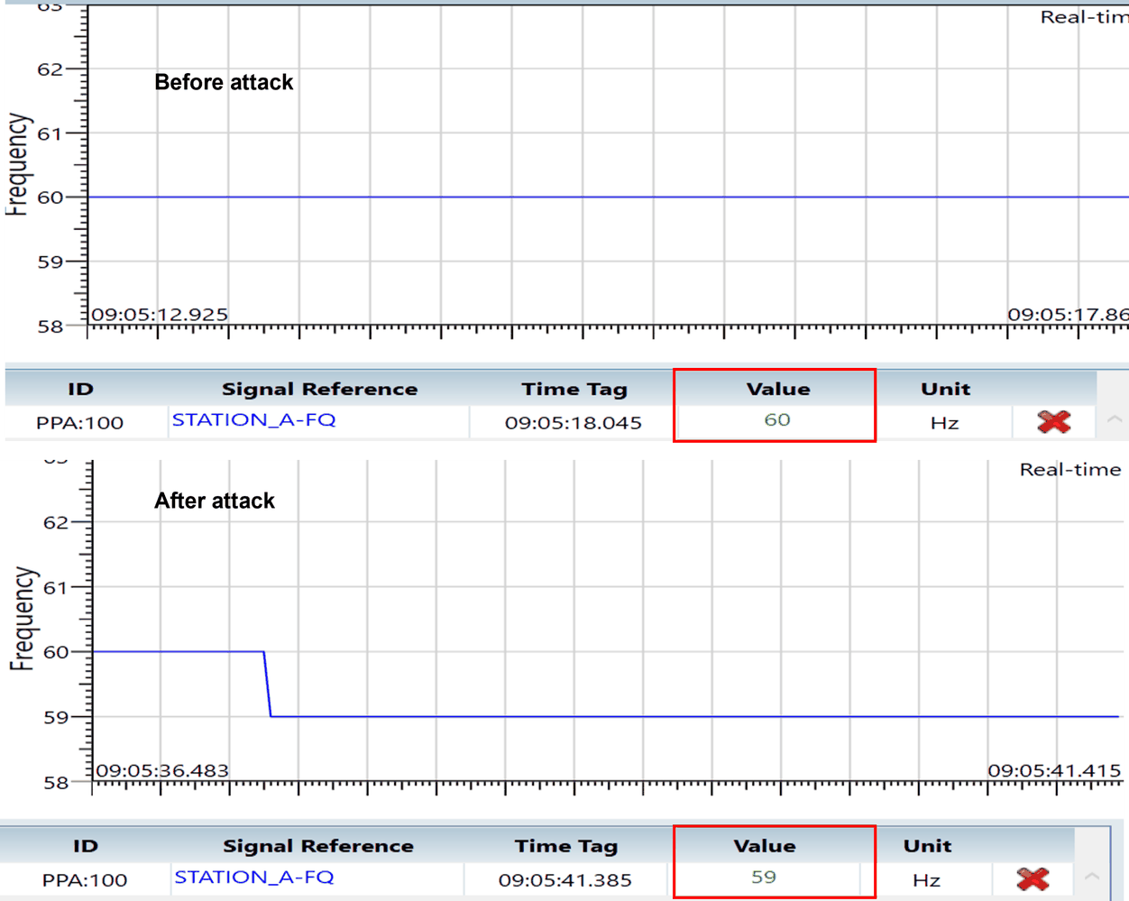
| Frequency override | The frequency field changes to the value that the attacker sets. |
| Manual injection | Magnitude, angle, frequency or ROCOF change to values that the user types in. |
IEEE 9-bus with MATLAB/Simulink
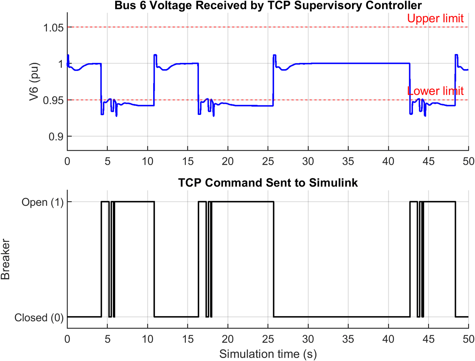
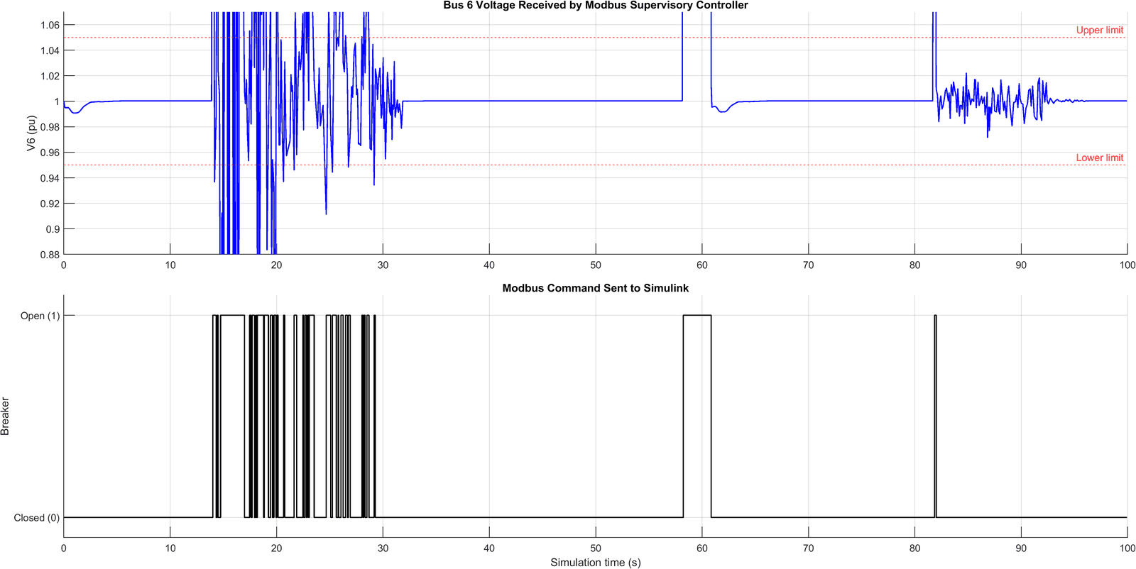
An IEEE 9-bus plant in Simulink sends the Bus 6 voltage to a MATLAB supervisory controller. The controller sends a breaker command back. NetSim Cyber applies false data injection (FDIA) to the voltage in the measurement path, and the controller acts on the false value. The same loop operates over TCP, UDP and Modbus TCP.
← Command path: the controller sends the breaker command back to Simulink. In these examples, the command path does not go through the Threat Agent.
Controller logic
0.95 pu ≤ V6 ≤ 1.05 pu → command 0 (close breaker) if not → command 1 (open breaker)These limits are settings for this example only. Do not use them as protection settings for a power system in operation.
Setup
- Plant
- IEEE 9-bus model in Simulink. Sample period 0.05 s.
- Tested with
- MATLAB R2023a, Instrument Control Toolbox, Windows 10/11 64-bit
- NetSim Cyber
- Two Real Nodes, one Threat Agent, one application filter
- Package
- Simulink model, controller scripts, Python packet modifier,
Wireshark Lua dissectors. Sample configuration
Cyber_IEEE 9-Bus_Example.
Three communication variants
| Variant | Measurement path | Command path | Attack | First trip in the plot |
|---|---|---|---|---|
| TCP | 24-byte frame to controller server, port 5001 | 18-byte frame from controller server, port 5002 | Python packet modifier ieee9bus_bus6_fdia.py: V6 − 0.07 pu | About 4.4 s |
| UDP | 24-byte datagram to port 5001 | 18-byte datagram, port 5003 to port 5002 | Same script: V6 − 0.07 pu | About 8.0 s |
| Modbus TCP | FC04 response from the Simulink server, port 502. Registers 0–1, FLOAT32 ABCD | FC05 write to coil 0 | Built-in Modbus attacker: Gaussian noise/jitter on FC04 addresses 0–1 | About 14.0 s |
The trip times come from the plots of the example runs. They are not measurements of protection performance.
Measurement frame and packet captures (TCP and UDP)
| Bytes | Field | Type | Description |
|---|---|---|---|
| 0–1 | Header | uint16 | Measurement-frame identifier |
| 2–5 | Sequence | uint32 | Frame number |
| 6–13 | Timestamp | double | Simulink simulation time, s |
| 14–21 | Bus 6 voltage | double | Voltage magnitude, pu. The packet modifier changes this field. |
| 22 | Breaker state | uint8 | 0 closed, 1 open |
| 23 | Status | uint8 | Frame status |
| Field, sequence 427 | PRE | MOD |
|---|---|---|
| Simulation time | 21.3 s | 21.3 s |
| Bus 6 voltage | 1.000321 pu | 0.930321 pu |
| Breaker state | Closed (0) | Closed (0) |
Multi-byte fields are little-endian. The breaker byte stays the same in the changed frame. The breaker change shows in a subsequent frame, after the controller command gets to Simulink.
Result
The controller acts on the value that it receives from the network. In the baseline runs, the attacker is off, the voltage stays near 1.0 pu, and the breaker stays closed. The plant-side Bus 6 scope shows the physical value, not the false network value.
Modbus replay
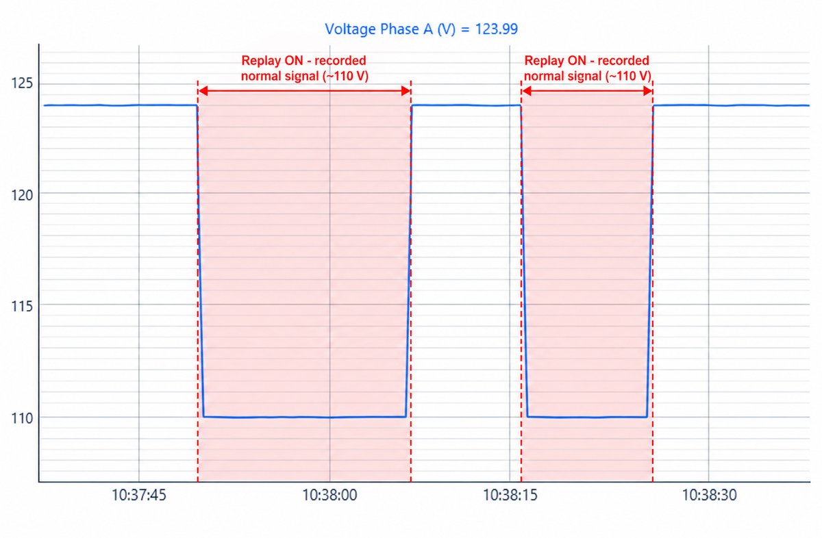
The Threat Agent records FC04 input-register responses while the Modbus Slave is in the Normal scenario. Then the Slave goes to the Overvoltage scenario. During replay, the Master receives the recorded values, and the overvoltage stays hidden.
Setup
- Experiment
Modbus_Replay, in the supplied workspace- Endpoint
127.0.0.1:502, Unit ID 1- Function
- FC04 Read Input Registers, start address 0, count 10
- Signals
- Voltage phases A, B and C, current, frequency. FLOAT32, ABCD byte order.
- Poll interval
- 500 ms
- Replay buffer
- 19 FC04 responses, a 9.5 s loop
Steps
- Start the Modbus Slave in the Normal scenario. Start the NetSim Cyber simulation, then start Master polling.
- In the Modbus attacker Replay tab, select FC04. Record, then stop. The attacker shows “Buffer is ready”.
- Set the Slave to the Overvoltage scenario. Phase voltages go to about 124 V, and the Master shows 124 V.
- Start replay. The attacker puts the next recorded body into each live FC04 response of the same length.
- Stop replay. The Master shows the live 124 V again.
| Step | Attacker mode | Slave | Master |
|---|---|---|---|
| Record | RECORD | Normal, about 110 V | Values from the Normal scenario, kept in the buffer |
| Overvoltage, before replay | OFF | Overvoltage, about 124 V | Live value near 124 V |
| Replay on | REPLAY | Stays near 124 V | Recorded signal near 110 V |
| Replay off | OFF | Stays near 124 V | Live value near 124 V |
Packet captures
Capture, tcp.port == 502 | Packets |
|---|---|
| PRE | 1008 |
| MOD | 80 replaced FC04 responses |
| POST | 1008 |
| DROP | 0 |
| Transaction ID 457 | PRE | MOD and POST |
|---|---|---|
| Byte count | 20 | 20 |
| TCP payload | 29 bytes | 29 bytes |
| First register pair | 17144, 288 | 17115, 64337 |
| Phase A voltage | 124.0022 V | 109.9909 V |
PRE and POST contain the same number of packets. For each packet that it gets, the Threat Agent forwards one changed live packet. It adds no replay packet. The transaction ID, Unit ID, function code and length stay the same. Only the register values change.
Conditions for replay
Replay applies only when the recorded body and the live body have the same length. Use the same function code, start address, count and poll interval when you record and when you replay. The loop time is the number of recorded responses multiplied by the poll interval.
Synchrophasor monitoring and defense
A Python Packet Modifier script starts the installed synchrophasor attacker. Then the script inspects the C37.118-2005 DATA frames that come from the attacker. If the measurements stay in the defense profile, the packet continues to the PDC. If a drop condition occurs, the script drops the full packet. The example operates with 50 Hz and 60 Hz PMUs.
Follow the packet
Move the diagram left or right to see all of it.
Modify, inspect, decide
Each packet that the Application Traffic Filter selects goes through one callback. In the callback, the attacker can change the payload. Then the callback inspects each complete frame and returns one verdict for the packet. Select a box in the diagram to read its function.
Setup
- PMU
- One C37.118-2005 station, PMU ID 7734, 50 Hz, 30 DATA frames/s,
CFG FORMAT
0x000E(floating-point phasors, frequency and ROCOF) - PDC
- PDC Manager on loopback TCP, PMU source port 4712
- Script
payload_modifier_synchrophasor2005_filter.py, the only Packet Modifier script. It starts the installed attacker.- Captures
- PRE, MOD, POST and DROP
- Version
- NetSim Cyber 15.1.11 or later
Callback contract
NETSIM_PACKET_API_VERSION = 2 selects the seven-argument
modify_payload() callback. Its context argument identifies the
TCP flow. The callback returns one dictionary for each packet:
modifiedTruewhen the callback changed payload bytesdropTrueto reject the packet and record it inDROP.pcapextra_delay_ms- Extra delay for the packet, in ms
Detection profile
| Measurement | Drop condition, 50 Hz PMU | Persistence |
|---|---|---|
| Frequency | Below 47.08 Hz or above 51.67 Hz | 0.16 s (5 samples at 30 frames/s) |
| ROCOF | Absolute reported or frequency-derived average above 3.0 Hz/s | Window of 0.1 s or more for each PMU |
| Undervoltage | Below 0.50 pu of the baseline | 2.0 s (60 samples at 30 frames/s) |
| Overvoltage | Above 1.20 pu of the baseline | 0.16 s (5 samples at 30 frames/s) |
Where the limits come from
The values come from IEEE Std 1547-2018. Table 18 gives the 60 Hz UF2 and OF2 values, 56.5 Hz and 62.0 Hz, each with a 0.16 s clearing time. For a 50 Hz PMU, the script scales them by 50/60, which gives 47.08 Hz and 51.67 Hz. A PMU that sets 60 Hz in CFG-2 uses 56.5–62.0 Hz directly.
Table 13 gives UV2 at 0.50 pu for 2.0 s and OV2 at 1.20 pu for 0.16 s. Table 21 gives the Category III ROCOF value of 3.0 Hz/s. IEEE Std 1547 does not give a procedure to discard packets. The example uses these values only as the limits of its profile.
These limits cannot tell a real grid disturbance from injected data. A production detector must also do protocol and consistency checks. Examples are C37.118 STAT flags, timestamp continuity, CRC validation and cross-measurement plausibility checks.
Results
| Test | Drop condition | Result |
|---|---|---|
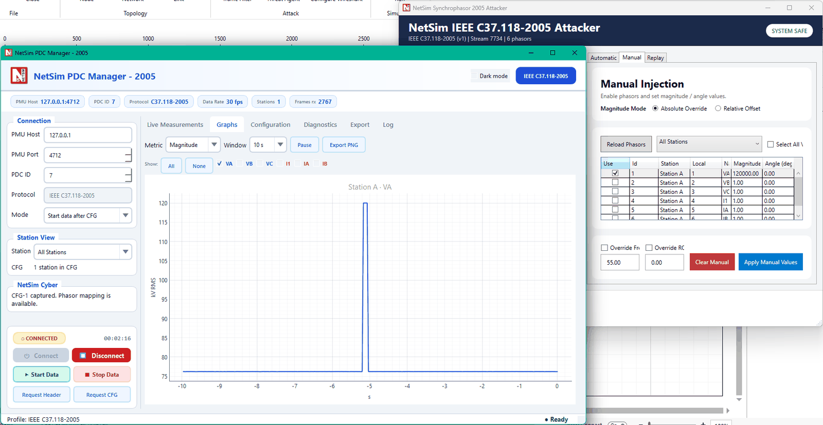
| Frequency, 55 Hz | The first condition that occurs. With a sudden override, the frequency-derived ROCOF condition usually occurs before the 0.16 s frequency condition. | Console shows the condition. Dropped packets go to DROP.pcap. |
| ROCOF, 5 Hz/s | One of the two 0.1 s ROCOF averages above 3.0 Hz/s | Console reports a ROCOF drop. The PDC holds its last accepted value. |
| Overvoltage, 120 kV | 0.16 s above 1.20 pu | The first persistence samples can get to the PDC. After that, the filter drops each packet in which the condition occurs. |
| Undervoltage, 30 kV | 2.0 s below 0.50 pu | The first persistence samples can get to the PDC. After that, the filter drops each packet in which the condition occurs. |
Packet-level operation
The verdict applies to the full IP packet. If a drop condition occurs for one station in a multi-station packet, the filter drops the full packet. The filter inspects TCP retransmissions, but each C37 SOC/FRACSEC sample counts one time only. A frequency or ROCOF condition stays latched until the filter gets 0.16 s of new safe samples.
Related pages
To use these examples on your setup, or to get more data about one, use the Tetcos contact page.
Trademarks
MATLAB and Simulink are registered trademarks of The MathWorks, Inc. Modbus is a trademark of Schneider Electric. Wireshark is a registered trademark of the Wireshark Foundation. All other product and company names are trademarks of their respective owners, used here only to identify the products discussed.