NetSim Cyber protocol simulators
Technical reference · current build
NetSim Cyber includes simulators for IEEE C37.118, Modbus TCP, DNP3, STTP and IEC 61850. For each protocol, a source application generates traffic, and a destination application receives, decodes and displays it. Both ends run on one Windows PC, or on two hosts on the same network. The NetSim Cyber page describes the attack library.
Back to NetSim CyberThe simulators
Select a protocol to open its reference. The ports are GUI defaults, and you can change them.
Setting up
How the applications start, what they need on the host, and how the two ends connect.
Launching
The Simulators window in NetSim Cyber lists Synchrophasor 2005, Synchrophasor 2011, DNP3, Modbus, R-GOOSE and STTP. Each entry starts its source and destination applications.
The IEC 61850 Testbed is a separate Windows application. The NetSim Cyber licence includes all the simulators.
Host requirements
- PMU, PDC Manager, Modbus: Python applications with a PySide6 GUI and pyqtgraph plots.
- DNP3, STTP, R-GOOSE: .NET 10 Windows desktop applications. DNP3 and STTP run a Python protocol backend.
- IEC 61850 Testbed: packaged executable, Windows 10 or 11 x64. GOOSE and SV need Npcap and Administrator rights.
Connecting the ends
For TCP protocols, the source binds to an address and port, and the destination connects to
it. On one PC, use 127.0.0.1. On two hosts, bind the source to its network
interface.
GOOSE and SV are Layer 2 multicast, so both ends share an Ethernet segment. R-GOOSE runs over UDP, unicast or multicast.
Executables and default ports
| Protocol | Source | Destination | Default transport | Protocol stack |
|---|---|---|---|---|
| C37.118.2-2005 | PMU-2005.pyw | PDC-Manager-2005.pyw | TCP 4712 | Built on pyPMU, extended by TETCOS |
| C37.118.2-2011 | PMU-2011.pyw | PDC-Manager-2011.pyw | TCP 4712 | Built on pyPMU, extended by TETCOS |
| Modbus TCP | Modbus-Slave.pyw | Modbus-Master.pyw | TCP 502 | In-house |
| DNP3 | outstation.exe | master.exe | TCP 20000 | In-house |
| STTP | STTP_Simulator.exe, publisher or subscriber role | TCP 18500 | Built on the GPA STTP Python library, extended by TETCOS | |
| R-GOOSE | RGooseSimulator.UI.exe, publisher and subscriber | UDP, set in the GUI | Built on libIEC61850, extended by TETCOS | |
| IEC 61850 Testbed | IEC61850_Testbed.exe, one tab per protocol | Ethernet, TCP 102, UDP 3788 | In-house | |
In-house: TETCOS wrote the protocol encoding and decoding. Built on X, extended by TETCOS: the named open-source library provides the protocol framing. TETCOS wrote the GUI, the signal generation and the additions listed in each tab.
Protocol reference
Roles, parameters, signal models and notes for each simulator.
IEEE C37.118 synchrophasor
Two PMU and PDC Manager pairs: the 2005 profile (frame version 1) and the 2011 profile (frame version 2). Both use pyPMU. TETCOS added the GUIs, multi-station streams, signal generation and CSV replay.
PMU-2005.pyw, PMU-2011.pyw
PDC-Manager-2005.pyw, PDC-Manager-2011.pyw
PMU Simulator, 2005 profile
- Stations per stream
- 1 to 32, each with its own IDCODE
- Phasor set
- Standard: IEC 60038 voltage levels (11 to 400 kV, default 132 kV) and 500 A at power factor 0.95 lagging. Custom: 1 to 64 phasors.
- Nominal frequency
- 50 Hz or 60 Hz, per station
- Data rate
- Per station, default 30 fps
- Signal source
- Generator or CSV replay (below)
- Network
- Bind address, TCP port
PMU Simulator, 2011 profile
- Stations per stream
- 1 to 8, each with its own IDCODE
- Phasors per station
- 1 to 64. Four give VA, VB, VC and I1. Higher counts generate the extra channel names.
- Nominal frequency
- 50 Hz or 60 Hz
- Data rate
- Per station
- Signal
- Balanced three-phase set, amplitude modulation at 0.1 Hz, depth in percent (default 5)
- Network
- Bind address, TCP port
PDC Manager
- Sends header, configuration and data start and stop commands. Data can start automatically after the configuration frame.
- Quality alarms: frequency deviation, repeated timestamps, stale data (no frame for more than 2 s), configuration change.
- You can export configuration frames to JSON and import them again.
Signal models, 2005 PMU
Statistical
Gaussian variation. Defaults: 0.02 Hz, 0.10°, 0.01 %. Seed 42 by default, so runs repeat exactly.
Sinusoidal
Amplitude modulation. Default rate 0.1 Hz and depth 2 %, both set in the GUI.
Frequency Step
After a delay (default 5 s), frequency ramps at −1 Hz/s to 1 Hz below nominal.
CSV replay
Streams recorded measurements, one row per frame. Stop, hold the last row, or loop at end of file.
CSV replay file format
- One row per frame, real and imaginary part per phasor, then frequency, df/dt and up to three analog values.
- The simulator detects polar form, degrees or radians, and V or kV from the file.
- The simulator validates the file before the stream starts.
In this build
- The simulators cover the 2005 and 2011 profiles. For 2024 streams, use an external PMU or openPDC. The NetSim Cyber attack library supports the 2024 profile.
- In the 2005 PMU, all stations in a stream share the first station's data rate and nominal frequency.
- The PDC Manager lists the analog and digital channels of each station. The live display and plots show phasor, frequency and ROCOF values.
Modbus TCP
An in-house Modbus TCP stack, written to the Modbus Application Protocol V1.1b. The slave serves a small feeder model and the master polls it.
Modbus-Slave.pyw
Modbus-Master.pyw
Slave register map
Slave
- Network
- Bind address and port, connected-client count and event log
- Scenarios
- Normal, Overvoltage, Fault, Breaker trip
- Signal override
- Set any input signal, and reset each one to its initial value
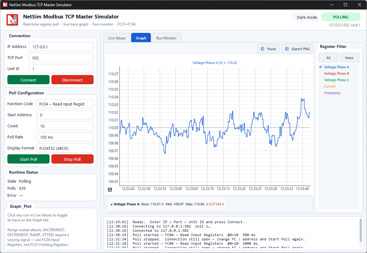
Master
- Poll
- Start address 0 to 65534, count 1 to 125
- Formats
- UINT16, INT16, HEX, BINARY, FLOAT32 in ABCD, CDAB, BADC, DCBA
- Tabs
- Live Values, Graph (filter, pause, PNG export, min, max, delta), Bus Monitor (TX and RX frames in hex)
- Labels
- Editable in
config\register_labels.json
Signal model and scenarios
Every 0.25 s, each input value takes a small random step. The model then pulls the value back toward its base value and clamps it. The register map and the voltage jitter follow a Modbus capture from a Typhoon HIL model.
step ~ N(0, (0.18 × band)²) reversion = 12 % of the distance to base, per update clamp = base ± 2 × band band = 0.03 % of base (voltages), 0.3 % of base (other signals)- Overvoltage Alarm: average voltage above 118 V.
- Fault Detected: current above 5.8 A, or average voltage below 100 V.
- System Healthy: the inverse of Fault Detected.
| Scenario | Voltage A, B, C | Current | Frequency | Other |
|---|---|---|---|---|
| Normal | 110 V | 5 A | 50 Hz | Power factor 1.0 |
| Overvoltage | 124.0, 123.5, 124.2 V | |||
| Fault | 98, 97, 96.5 V | 6.2 A | 49.2 Hz | Power factor 0.82, opens Breaker 1 |
| Breaker trip | Opens all three coils |
In this build
- The Master polls with the read function codes FC01 to FC04. The Slave also accepts the write codes FC05, FC06, FC15 and FC16 from any Modbus client.
- The Bus Monitor shows each frame, MBAP header and PDU, as hex.
DNP3
An in-house DNP3 stack to IEEE 1815-2012, with a master and an outstation. The outstation runs a small feeder model.
outstation.exe
master.exe
Protocol stack
Object groups
Outstation
- Binary inputs 0–3
- CB1 Main Breaker, CB2 Feeder Breaker, DS1 Isolator, ES1 Earth Switch
- Analog inputs 0–3
- Voltage (V), Current (A), Active Power (W), Temperature (°C)
- Counters 0–1
- Energy (Wh), Breaker Ops
- Outputs
- Binary outputs 0–3, analog outputs 0–1, set by the master
- Also
- Point flags, class 1–3 event buffers, manual override, unsolicited status, activity log
Master
- Integrity poll
- Class 0, 1, 2 and 3
- Event poll
- Class 1, 2 and 3
- Acquisition
- Polling (interval or on demand), unsolicited only, or both. The master confirms unsolicited responses automatically.
- Controls
- Binary output (CROB) and analog output by index. Select before operate or direct operate. Optional repeat on a timer
- Display
- Point table, trend graph, communication log
Feeder model
- The breaker trips with a 1 % chance per update. The outstation logs the trip, and Breaker Ops increments.
- The outstation generates events only past a deadband: 0.8 V, 0.5 A, 25 W, 0.6 °C.
In this build
- Manual override applies to binary inputs, analog inputs and counters. Outputs follow the master's commands.
STTP
The Streaming Telemetry Transport Protocol, IEEE 2664. One application takes the publisher role or the subscriber role. It uses the Grid Protection Alliance STTP Python library. TETCOS added the GUI, the simulated measurements and the trend display.
STTP_Simulator.exe
STTP_Simulator.exe
Publisher
- Port
- Default 18500
- Publish interval
- Milliseconds, default 1000
- Options
- Auto start, metadata on connect
- Measurements
- Six signals (below)
Subscriber
- Connection
- Host (default
localhost), port 18500 - Metadata
- On connect, or on request
- Filtering
- STTP filter expressions. Resubscribe without reconnecting
- Display
- Table (ID, name, signal reference, value, adjusted value, timestamp), trend graph, communication log
Signal model
All six signals derive from one phase accumulator φ, which advances by 0.06 each publish cycle.
In this build
- The publisher sends uncompressed payloads, so you can read the measurements directly in a packet capture.
IEC 61850
Two applications. The in-house IEC 61850 Testbed covers GOOSE, Sampled Values, MMS and R-GOOSE, and has an attack tab. The R-GOOSE Simulator, built on libIEC61850, covers R-GOOSE with encryption and signatures.
IEC 61850 Testbed
IEC61850_Testbed.exe
· TETCOS code BER-encodes the PDUs. Scapy sends and captures the raw Ethernet frames.
GOOSE
- Publisher and subscriber
- Dataset of bool, int or float entries
- Send Once raises stNum. Continuous publishing raises sqNum.
Sampled Values
- Publisher and subscriber
- Three-phase sine, 80 samples per cycle by default
- Subscriber plots the waveform and counts sample gaps
MMS
- IED server and SCADA client
- Initiate, GetNameList, Read, Write
- 14 variables in LLN0, XCBR1, MMXU1, PTOC1
R-GOOSE
- Publisher and subscriber
- Multicast 239.0.0.1 by default
- Security: none or HMAC-SHA256-80
Testbed fields and defaults
| Protocol | Fields (defaults) | Receiver display |
|---|---|---|
| GOOSE | Interface, APPID (0x1001), VLAN ID, source and destination MAC (01:0c:cd:01:00:01), control block and dataset references, confRev, retransmit interval (4 ms) | Time, APPID, stNum, sqNum, control block, entry count, state-change and simulation flags |
| Sampled Values | Interface, APPID (0x4001), MACs, SV ID, samples per cycle (80), frequency (50 Hz), voltage amplitude (63508 mV), current amplitude (1000 mA). One ASDU, channels Ia, Ib, Ic, In, Va, Vb, Vc, Vn. | Packets, sample gaps, smpCnt, APPID, value and quality per channel, waveform |
| MMS | Server: listen address, port 102. Client: host, port, variable name, value and type (int, float, bool). | Live data-model tree on the server |
| R-GOOSE | Destination IP (239.0.0.1), port 3788, source IP, APPID, control block and dataset references, confRev, retransmit interval, simulation flag, HMAC key | Packets, stNum changes, HMAC result, message table |
Attacks tab (11 attacks)
| Protocol | Attack | Parameters |
|---|---|---|
| Sampled Values | False data injection | Interface, APPID, voltage and current scale (2.0), duration, frequency |
| Sampled Values | Replay | Interface, capture time, repeat count |
| MMS | Unauthorized write | Host, port, variable (IED1/XCBR1$CO$Pos$ctlVal), value, type |
| MMS | Enumeration, read scan, DoS | Host, port. DoS repeats connect and disconnect. |
| R-GOOSE | Spoof | Destination, port, source IP, APPID, control block, count, interval. stNum is set to 9999. |
| R-GOOSE | Replay | Destination, port, count, interval |
| R-GOOSE | Flood | Destination, port, APPID, control block, duration |
| R-GOOSE | HMAC bypass | Sends frames with the security algorithm set to none |
| R-GOOSE | stNum manipulation | Rollback mode, count |
R-GOOSE Simulator
Encryption
Signature
- Publisher
- Name, GoCB reference, GoID, dataset reference, APPID, confRev, timeAllowedToLive, publish interval, simulation flag
- Network
- Unicast or multicast, local and destination address and UDP port
- Controls
- Start, stop, publish once, trigger event (raises stNum), automatic publishing
- Dataset editor
- Boolean, integer and timestamp entries, with templates
- Keys
- Key ID, ASCII or hex key, test key generation, copy to subscriber
- Subscriber
- GoCB reference, bind address and port, multicast group, live stNum, sqNum, validity and TTL
- Scenarios
- Saved and loaded as JSON
In this build
- Testbed GOOSE retransmits at the configured fixed interval.
- The Testbed GOOSE subscriber reports the dataset entry count for each message.
- MMS covers the Initiate, GetNameList, Read and Write services on the built-in 14-variable model.
- Enter the stream settings in the GUI. The Testbed does not import SCL files.
- For AES-GCM encryption and the other signature types, use the R-GOOSE Simulator.
Use with the Threat Agent
The simulators are the endpoints of a NetSim Cyber scenario. The Threat Agent sits in the path between them.
Protocol testing
Run the two simulators without the Threat Agent to check decoding, polling and frame rates.
Attack injection
Put the Threat Agent in the path to modify, delay, replay or drop selected fields while the session stays up. See the attack reference.
Devices and HIL
Replace either endpoint with a device or a real-time simulator, such as a PMU, IED, RTU, PLC, Typhoon HIL, OPAL-RT or RTDS. The attack configuration stays the same.
The worked examples use the PMU, PDC Manager and Modbus simulators with the Threat Agent. To see a simulator run, or to check whether it fits a test setup, contact Tetcos.
Sources and trademarks
Source. The values on this page come from the source code of the current simulator build. Defaults can change between releases.
Open-source components. The C37.118 simulators use pyPMU. The STTP simulator uses the STTP Python library from the Grid Protection Alliance. The R-GOOSE Simulator uses libIEC61850. The IEC 61850 Testbed uses Scapy for raw frame input and output. Each is used under its own licence.
Trademarks. Typhoon HIL is a trademark of Typhoon HIL, Inc. OPAL-RT is a trademark of OPAL-RT Technologies, Inc. RTDS is a trademark of RTDS Technologies Inc. openPDC is a product of the Grid Protection Alliance. Modbus is a trademark of Schneider Electric. All other product and company names are trademarks of their respective owners, used here only to identify the products discussed.