Featured Examples
NetSim provides inbuilt examples to get started with the SDN module. To access these examples, you can go to Examples > Software-Defined-Networks in the NetSim Home Screen. You can change the default values of the parameters in these examples and see how they affect the performance of the SDN network.
Configuring SDN
Configuring One SDN Controller in a Simple Internetwork
The Internetwork model in this example consists of the following configuration:
A subnet with 2 wired nodes, 3 routers, and a unicast application running on one of the wired nodes.
Only one router is configured as the SDN controller.
Open Flow protocol is enabled on all wired nodes and routers.
A unicast application is set between Wired Node 1 to Wired Node 2.
Set Transport Protocol to TCP in Application Properties.
Simulation time is set to 500 seconds.
Packet trace is enabled.
To simulate the example for One SDN controller in an Internetwork:
Open NetSim and Select Examples > Software Defined Networks > Configuring SDN > SDN Internetworks then click on the tile in the middle panel to load the example as shown in below

The following network diagram illustrates what the NetSim UI displays when you open the example configuration file for SDN as shown Figure 1.

In the application layer of the SDN Controller node:
SDN Controller option set to TRUE.
Open Flow protocol is enabled.
The following image illustrates the settings done in the SDN controller device:

In the other devices (Routers and wired node) that are part of the network,
SDN Controller option is set to FALSE.
SDN Controller DeviceName is set as “SDN Controller” which is the name of the controller node.
Open Flow protocol is enabled.
The following image illustrates settings done in the other devices:

The following table lists the settings done in all the devices that are part of the network:
| Device Name | Open Flow | SDN Controller | SDN Controller DeviceName |
|---|---|---|---|
| Wired Node 1 | Enable | FALSE | SDN Controller |
| Router 3 | Enable | FALSE | SDN Controller |
| SDN Controller | Enable | TRUE | NA |
| Router 5 | Enable | FALSE | SDN Controller |
| Wired Node 2 | Enable | FALSE | SDN Controller |
Configure an application between any two nodes in the scenario by selecting an application from the Set Traffic tab.
CBR Application from Wired Node 1 to Wired Node 2 with 50 Mbps Generation Rate (Packet Size: 1460Bytes, Inter Arrival Time: 233.6\(\mu\)s).
Set Transport Protocol to TCP.
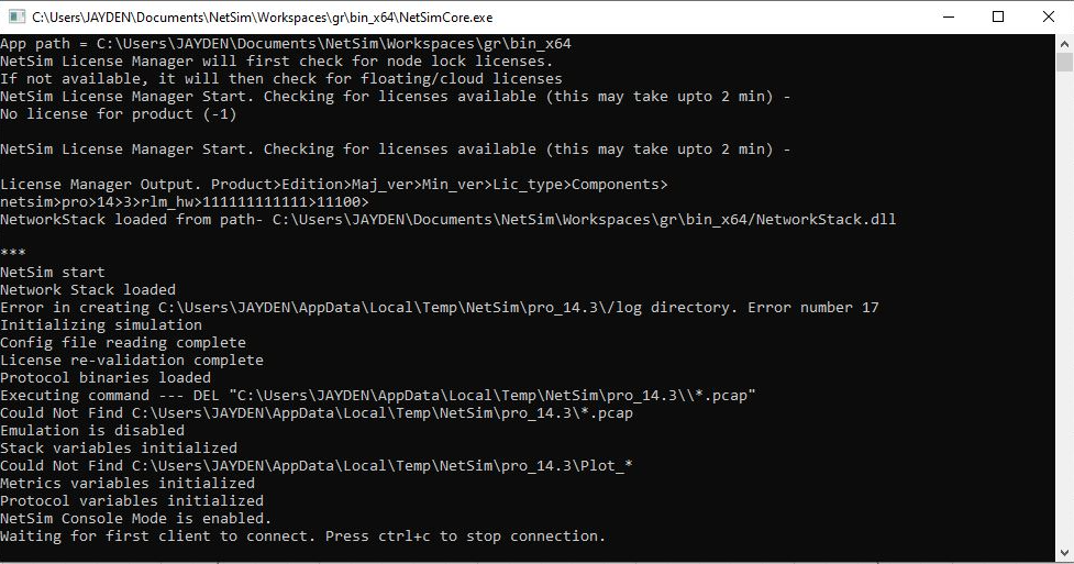
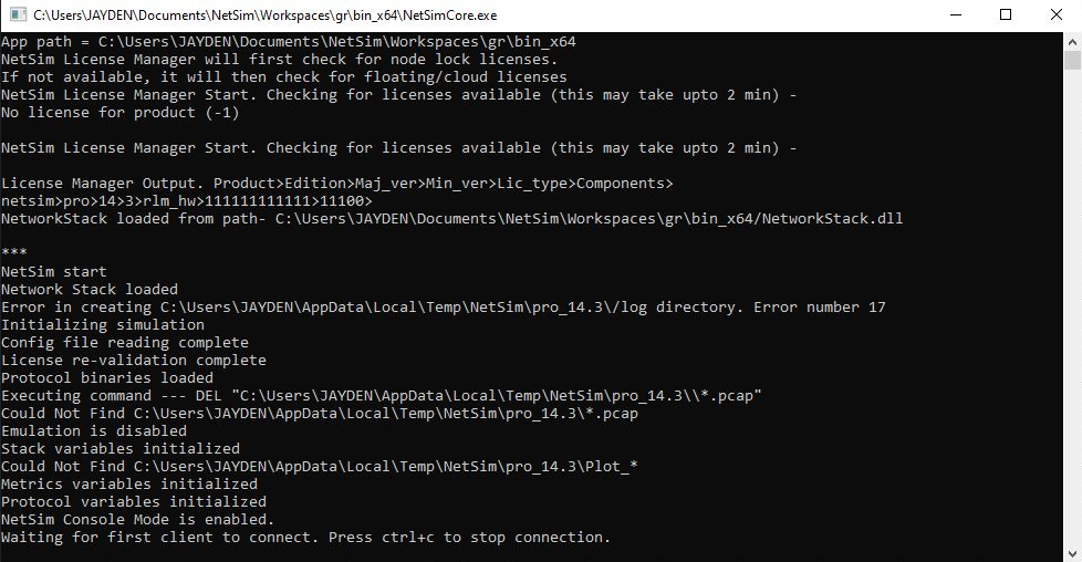
Before simulating the example, Right-click SDN Controller and select NetSim Console. Now, the client (NetSimCLI.exe) waits to establish a connection with NetSimCore.exe as shown below.

Follow the below steps to simulate an example.
Click on the Options tab. Select Run time interaction.

In the Run Time Interaction tab, set Interactive Simulation to True and click on OK.

Click on Run Simulation window and simulate it to 500 secs.

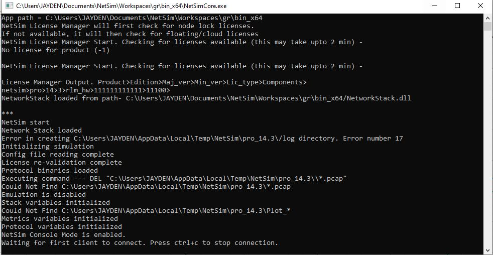
Simulation (NetSimCore.exe) starts to run. NetSimCore.exe displays the following message: waiting for the first client to connect.
Use this console to execute SDN commands as explained in section 2.2.
Configuring Multiple SDN Controllers in a Wireless Sensor Network
In this example, multiple SDN controllers are configured in a Wireless Sensor Network.
The Wireless Sensor Network model in this example consists of the following configuration:
A subnet with 4 wireless sensors, 1 ad-hoc link, 1 WSN sink node, and a unicast sensor application running on one of the wireless sensors.
Set Transport Protocol to TCP in Application Properties.
Two wireless sensors are configured as SDN controllers.
Open Flow protocol is enabled on all wireless sensors and sink node.
NetSim uses the following defaults for this SDN example:
The unicast application transmits data from Wireless Sensor 3 to Wireless Sensor 5.
Simulation runs for 500 seconds.
Packet trace is enabled.
NOTE: For a WSN network, ping command is not supported on ZigBee device since these nodes do not support ICMP protocol.
To simulate the example for multiple SDN controllers in WSN for SDN:
Open NetSim and Select Examples > Software Defined Networks > Configuring SDN > WSN Setting Multiple SDN Controllers then click on the tile in the middle panel to load the example as shown in below screenshot
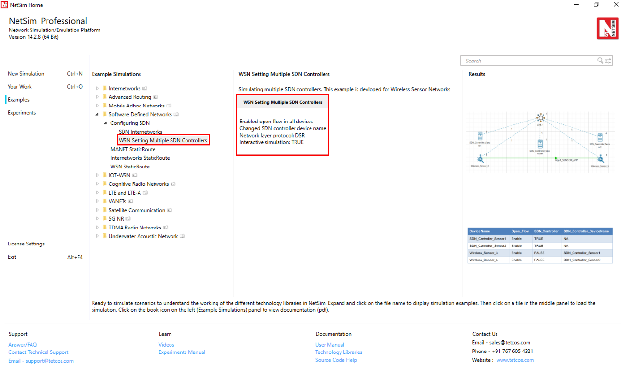
The following network diagram illustrates the network setup related to this example as shown below.

The SDN Controller Sensors, Wireless Sensors and the sinknode are configured as SDN controllers with Open Flow protocol enabled in all the nodes.
The following image illustrates the settings done in the sensors configured as SDN controller as shown below.

The sensor SDN Controller Sensor 1 is set as the SDN controller for Wireless Sensor 3 and SDN Controller Sensor 2 is set as the SDN controller for Wireless Sensor 5.
The following image illustrates the settings done in sensor 3.

The following table lists the default setting for the wireless sensors.
| Device Name | Open Flow | SDN Controller | SDN Controller DeviceName |
|---|---|---|---|
| SDN Controller Sink Node | Enable | TRUE | NA |
| SDN Controller Sensor1 | Enable | TRUE | NA |
| SDN Controller Sensor2 | Enable | TRUE | NA |
| Wireless Sensor3 | Enable | FALSE | SDN Controller Sensor1 |
| Wireless Sensor5 | Enable | FALSE | SDN Controller Sensor2 |
Configure an application between any two nodes in the scenario by selecting an application from the Set Traffic tab.
Sensor Application from Wireless Sensor 3 to Wireless Sensor 5 with Packet Size: 50Bytes, Inter Arrival Time: 1000000\(\mu\)s).
Set Transport Protocol to TCP.
Packet trace is enabled under configure reports tab.
To use the SDN CLI Console:
Right-click SDN Controller Sensor1 or SDN Controller Sensor2 and click NetSim Console. Now, the client (NetSimCLI.exe) starts and tries to establish a connection with NetSimCore.exe.
The following image illustrates the NetSim CLI console.

Simulate the example. To do so:
Click on the Options tab. Select Run time interaction.
In the Run time Interaction tab, Interactive Simulation option is set to True and click on OK.
Click on the Run Simulation window and simulate it to 500 sec.

You can execute various SDN commands that are supported in any of the SDN controller Sensor CLI.
Configuring Static Routes for a MANET Network by using SDN
In this example static routes are configured using the SDN controllers, in a MANET network.
The MANET network model in this example consists of the following configuration:
A subnet with 5 wireless nodes and 1 ad-hoc link, and a unicast CBR application running on one of the wireless nodes.
DSR is the routing protocol that is enabled on all wireless nodes.
One wireless node is configured as the SDN controller.
Wireless nodes do not have mobility.
A unicast application is configured from Wireless Node 1 to Wireless Node 5.
Simulation time is set to 500 seconds.
Packet trace is enabled.
To simulate the example for MANET using SDN:
Open NetSim and Select Examples > Software Defined Networks > MANET StaticRoute then click on the tile in the middle panel to load the example as shown in below screenshot
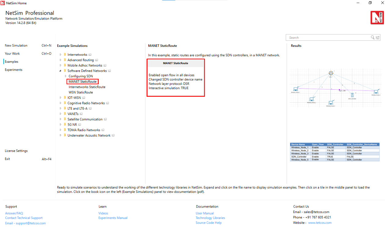
The following network diagram illustrates the network setup.

DSR routing protocol is configured in Network layer for all the nodes and set the nodes to be stationary.
Mobility model is set to NO MOBILITY in all the nodes.
ICMP protocol is enabled in the network layer properties of all the wireless nodes.
Open flow protocol is enabled in all the wireless nodes.
The following settings were done in the wireless nodes to configure Wireless Node 4 as SDN controller and other nodes as its clients.
| Device Name | Open Flow | SDN Controller | SDN Controller DeviceName |
|---|---|---|---|
| Wireless Node 1 | Enable | FALSE | SDN Controller |
| Wireless Node 2 | Enable | FALSE | SDN Controller |
| Wireless Node 3 | Enable | FALSE | SDN Controller |
| SDN Controller | Enable | TRUE | N/A |
| Wireless Node 5 | Enable | FALSE | SDN Controller |
Configure an application between any two nodes in the scenario by selecting an application from the Set Traffic tab.
CBR Application from Wireless Node 1 to Wireless Node 5 with 0.584 Mbps Generation Rate (Packet Size: 1460Bytes, Inter Arrival Time: 20000\(\mu\)s).
Set Transport Protocol to UDP.
Click on link, expand the right-side property panel and set Channel Characteristics: Path Loss Only, Path Loss Model: Log Distance, Path Loss Exponent: 2.5.
In NetSim Packet Trace is enabled under configure reports tab.
To use the SDN CLI Console:
Right-click SDN Controller and select NetSim Console. Now, the client (NetSimCLI.exe) starts and attempts to establish a connection with NetSimCore.exe.
Simulate the example. To do so:
Click on the Options tab. Select Run time interaction.
In the Run time Interaction tab, Interactive Simulation option is set to True and click on OK.
Click on Run simulation window and simulate it to 500 sec.
Simulation (NetSimCore.exe) starts to run. NetSimCore.exe displays the following message: waiting for the first client to connect.
Interpret the Results
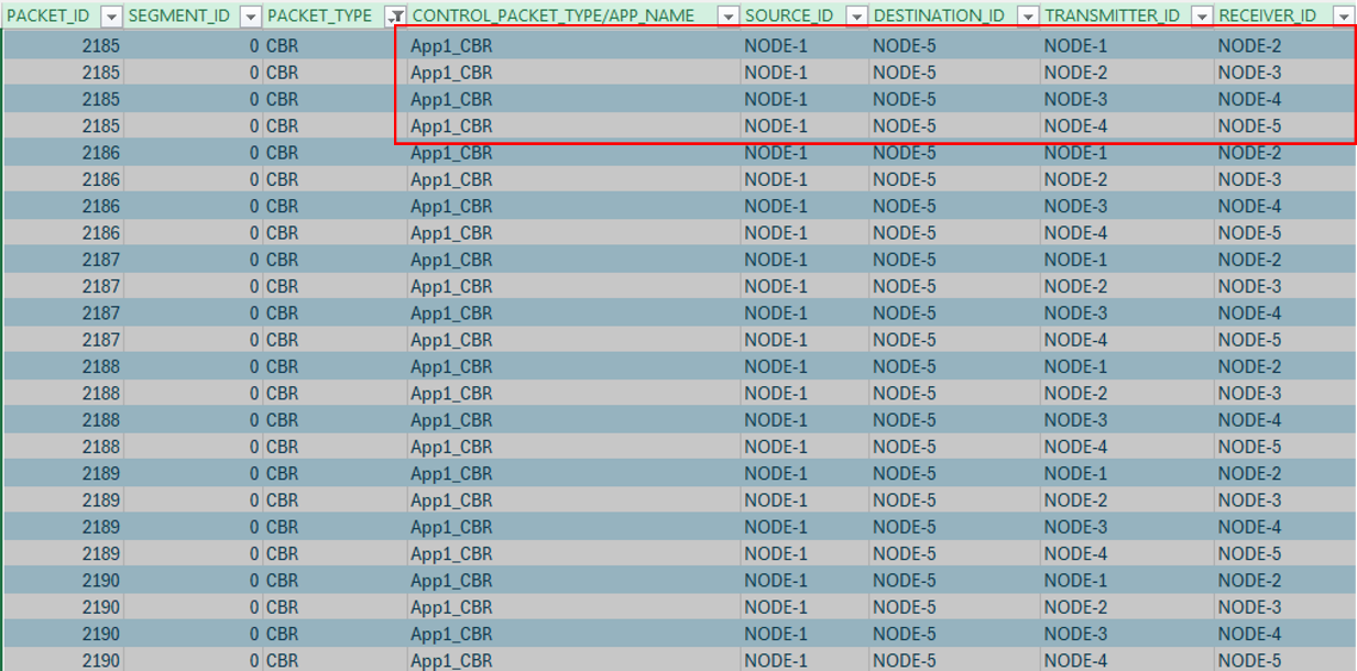
In the simulation results window select the Traces option in the left area and open the packet trace file. Once the packet trace opens apply filter in the CONTROL PACKET TYPE/APP NAME for APP1 CBR.
The packets reach Wireless Node 5 from Wireless Node 1-> Wireless Node 3-> Wireless Node 5.

For the same example, configure static routes such that the packets will go through Wireless Node 1 > Wireless Node 2, Wireless Node 3, SDN Controller to Wireless Node 5. To configure the static routes on SDN Controller for all the nodes.
Right-click SDN Controller and select NetSim Console.
Re-run the simulation.
Type the following commands on the NetSim CLI console, in the
<DeviceName with Device ID> route add <destination IP address> MASK <subnet mask> <gateway IP address> <metric> if <interface #>format.Wireless_Node_1 route ADD 192.168.0.6 MASK 255.255.255.0 192.168.0.3 METRIC 1 IF 1Wireless_Node_2 route ADD 192.168.0.6 MASK 255.255.255.0 192.168.0.4 METRIC 1 IF 1Wireless_Node_3 route ADD 192.168.0.6 MASK 255.255.255.0 192.168.0.5 METRIC 1 IF 1SDN_Controller route ADD 192.168.0.6 MASK 255.255.255.0 192.168.0.6 METRIC 1 IF 1

Interpret the Results.
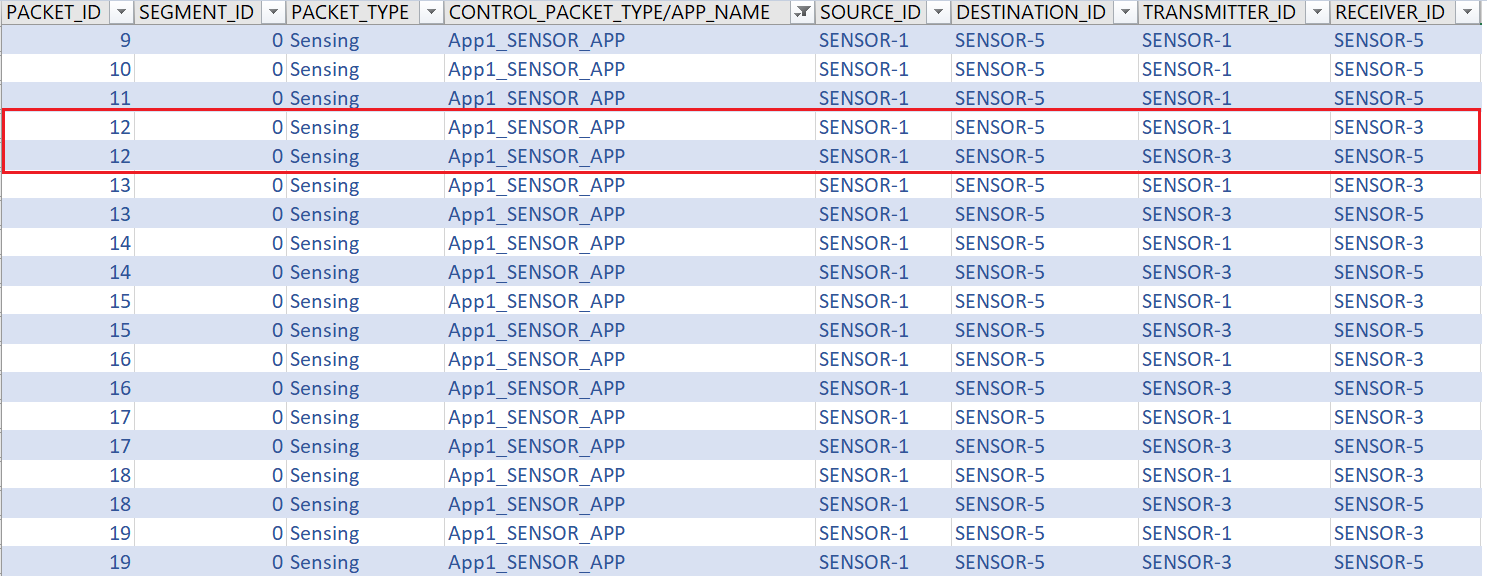
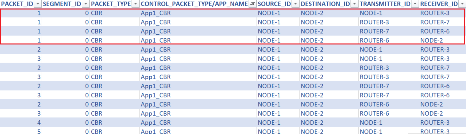
Open Packet trace and filter CONTROL PACKET TYPE/APP NAME to APP1 CBR, you will see that data packets transmitted from Wireless Node 1 > Wireless Node 2 > Wireless Node 3 > SDN Controller to Wireless Node 5 as part of the commands executed for static route configuration.
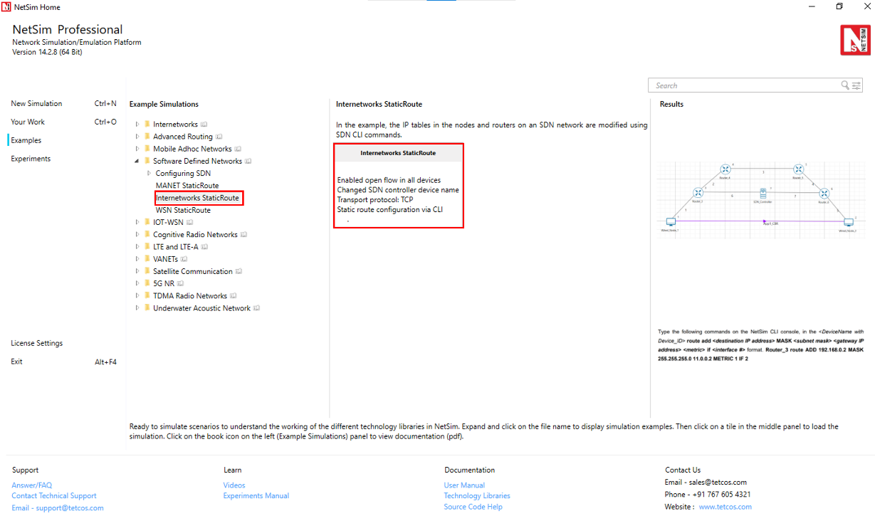
Configuring Static Routes for Internetworks using SDN
In the example the IP tables in the nodes and routers on an SDN network are modified using SDN CLI commands.
The network model in this example consists of the following configuration:
A subnet with 2 wired nodes, 5 routers, and a unicast application running on one of the wired nodes.
SDN controller running on one of the router.
Set Transport Protocol to TCP in Application. Open Flow protocol is enabled on all wired nodes and routers.
A unicast application set from Wired Node 1 to Wired Node 2.
OSPF is the routing protocol in the routers.
The node SDN Controller is configured to be the SDN controller.
Simulation time is set to 500 seconds.
Packet trace, and Event trace are enabled.
To simulate SDN and change the IP tables:
Open NetSim and Select Examples > Software Defined Networks > Internetworks StaticRoute then click on the tile in the middle panel to load the example as shown in below screenshot.
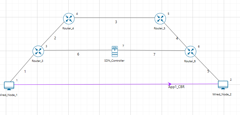
The following network diagram illustrates the network setup related to this example.
Configure an application between any two nodes in the scenario by selecting an application from the Set Traffic tab.
CBR Application from Wired Node 1 to Wired Node 2 with 50 Mbps Generation Rate (Packet Size: 1460Bytes, Inter Arrival Time: 233.6\(\mu\)s).
Application Start time is 30 sec.
Set Transport Protocol to TCP.
Packet Trace and Event Trace features are enabled from Configure Reports.
To use the SDN CLI: Right-click SDN Controller and select NetSim Console. Now, the client (NetSimCLI.exe) starts and attempts to establish a connection with NetSimCore.exe.
Simulate SDN. To do so,
In the Run time Interaction under options tab, Interactive Simulation option is set to True.
Click the Run button. The Run Simulation pop-up window appears.
Simulation time is set to 500 Seconds.
Interpret the results.
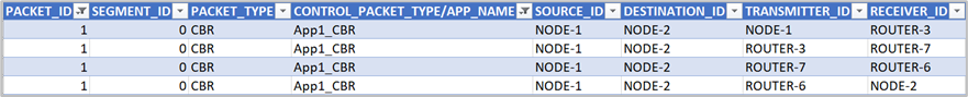
Open packet trace and filter the CONTROL PACKET TYPE/APP NAME to APP1 CBR, and PACKET ID to 1. Packets reach Wired Node 2 via Wired Node 1 > Router 3 > SDN Controller > Router 6.
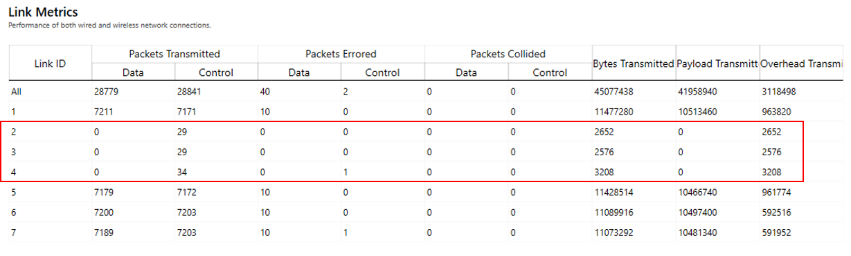
Click View Results on the tool bar, Link metrics in the left area and check the Detailed View check box in the Link Metrics Table pop-up window. You will not see data packet transmissions in links 2, 3, and 4 as shown in below Figure.
For the same example, configure static routes on Router 3 such that all traffic bound for the 11.0.0.18 subnet will go to a gateway 11.0.0.2, that is, from Router 3 > Router 4 > Router 5 > Router 6.
To configure the static routes for Router 3:
Simulate the network again by following below steps
Now, right-click SDN Controller and click NetSim Console.
Now, the client (NetSimCLI.exe) starts and attempts to establish a connection with NetSimCore.exe. NetSim CLI console opens.
Type the following commands on the NetSim CLI console, in the
<DeviceName with Device ID> route add <destination IP address> MASK <subnet mask> <gateway IP address> <metric> if <interface #>format.Router_3 route ADD 192.169.0.2 MASK 255.255.255.0 11.0.0.2 METRIC 1 IF 2(Optional) To check the static routes on ROUTER 3, type
ROUTER_3 route print. The following image illustrates step (c) and (d).

Interpret the results.
Click packet trace from the results dashboard.
The packets reach Wired Node 2 via Router 3 > Router 4 > Router 5 > Router 6.
Click Link metrics in the left area and check the Detailed View check box in the Link Metrics Table pop-up window.
You will see data packet transmissions in Links 2, 3, and 4.
The following figure illustrates step (7c) as shown in below.

In the simulation results window click on the Open Packet trace option in the left area. Once the packet trace opens, apply display filters to the CONTROL PACKET TYPE/APP NAME column to show only OPENFLOW COMMAND and OPENFLOW RESPONSE packets.
You will see that OpenFlow packets flow between Router 3 to SDN Controller.
In Router 3 under application layer use routing protocol as RIP
Configure static routes for Router 3 as follows:
Simulate SDN (Refer step 4).
Right-click SDN Controller and click NetSim Console.
Now, the client (NetSimCLI.exe) starts and tries to establish a connection with NetSimCore.exe. NetSim CLI console opens.
Type the following commands on the NetSim CLI console, in the
<DeviceName with Device ID> route add <destination IP address> MASK <subnet mask> <gateway IP address> <metric> if <interface #>format.
Router_3 route ADD 192.169.0.2 MASK 255.255.255.0 11.0.0.26 METRIC 1 IF 2
Interpret the results.
Click View Packets and see the Packet Trace. The packets reach Wired Node 2 via Router 3 > SDN Controller > Router 6.
Configuring Static Routes for a WSN Network by using SDN
In this example static routes are configured in sensors using SDN commands executed in a SDN controller.
The WSN network model in this example consists of the following configuration:
A subnet with 5 wireless sensor, 1 ad-hoc link, 1 wireless sink node, and a unicast sensor application running on one of the wireless sensors.
One wireless Sensor is configured as the SDN controller.
A unicast application from Wireless Sensor 1 to Wireless Sensor 5.
Simulation time of 500 seconds.
Packet trace is enabled.
To simulate the example for WSN using SDN:
Open NetSim and Select Examples > Software Defined Networks > WSN StaticRoute then click on the tile in the middle panel to load the example as shown in below screenshot
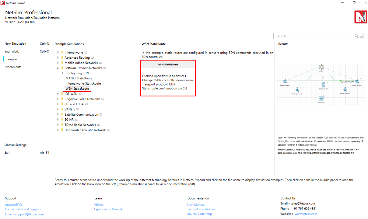
The following network diagram illustrates the network setup considered in this example:

The following settings are done in the application layer properties of the devices for configuring SDN:
| Device Name | Open Flow | SDN Controller | SDN Controller DeviceName |
|---|---|---|---|
| Wireless Sensor 1 | Enable | FALSE | SDN Controller |
| Wireless Sensor 2 | Enable | FALSE | SDN Controller |
| SDN Controller | Enable | TRUE | NA |
| Wireless Sensor 4 | Enable | FALSE | SDN Controller |
| Wireless Sensor 5 | Enable | FALSE | SDN Controller |
| WSN Sink 6 | Enable | FALSE | SDN Controller |
Configure an application between any two nodes in the scenario by selecting an application from the Set Traffic tab.
Sensor Application from Wireless Sensor 1 to Wireless Sensor 5 with default Generation Rate (Packet Size: 50Bytes, Inter Arrival Time: 1000000\(\mu\)s).
Set Transport Protocol to UDP.
Before Simulating the scenario, Right-click SDN Controller and click NetSim Console. Now, the client (NetSimCLI.exe) waits to establish a connection with NetSimCore.exe.
Enable the packet trace from the Configure Reports tab and click on the Options tab and select Run time interaction.
In the Run time Interaction tab, Set the Interactive Simulation option as True and click on OK.
Click on Run simulation window and simulate it to 500 sec.
Simulation (NetSimCore.exe) starts to run. NetSimCore.exe displays the following message: waiting for the first client to connect.
Observe the packet trace after simulation, you will see the direct communication between wireless sensor 1 and 5.
For the same example, configure static routes such that the packets will go through Wireless Sensor 1 to Wireless Sensor 5 via SDN Controller. To configure the static routes in SDN Controller for Wireless Sensor 1 follow the above step 3 as explained above
Type the following commands on the NetSim CLI console, in the
<DeviceName with Device ID> route add <destination IP address> MASK <subnet mask> <gateway IP address> <metric> if <interface #>format.Wireless_Sensor_1 route ADD 192.168.0.6 MASK 255.255.255.0 192.168.0.4 METRIC 1 IF 1SDN_Controller route ADD 192.168.0.6 MASK 255.255.255.0 192.168.0.6 METRIC 1 IF 1
Interpret the results.
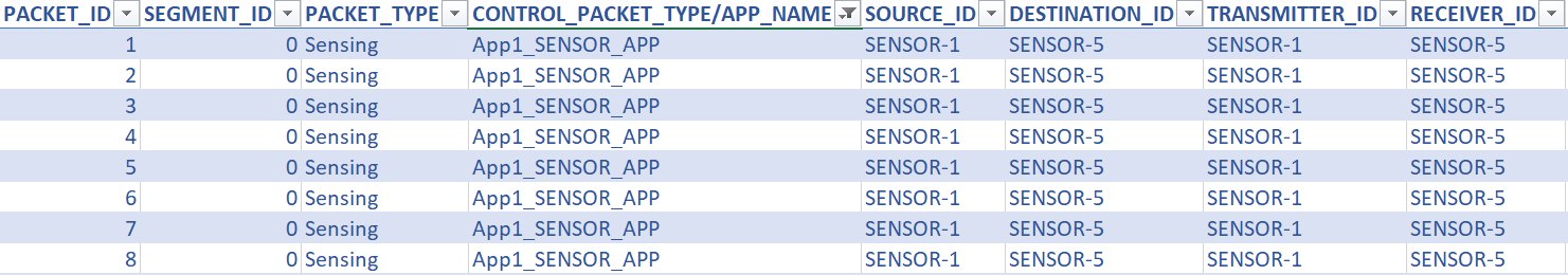
Open Packet trace and filter the CONTROL PACKET TYPE/APP NAME to show only APP1 SENSOR APP, you will see that data packet flow from wireless sensor 1 to wireless sensor 5 through SDN Controller.