Simulation GUI
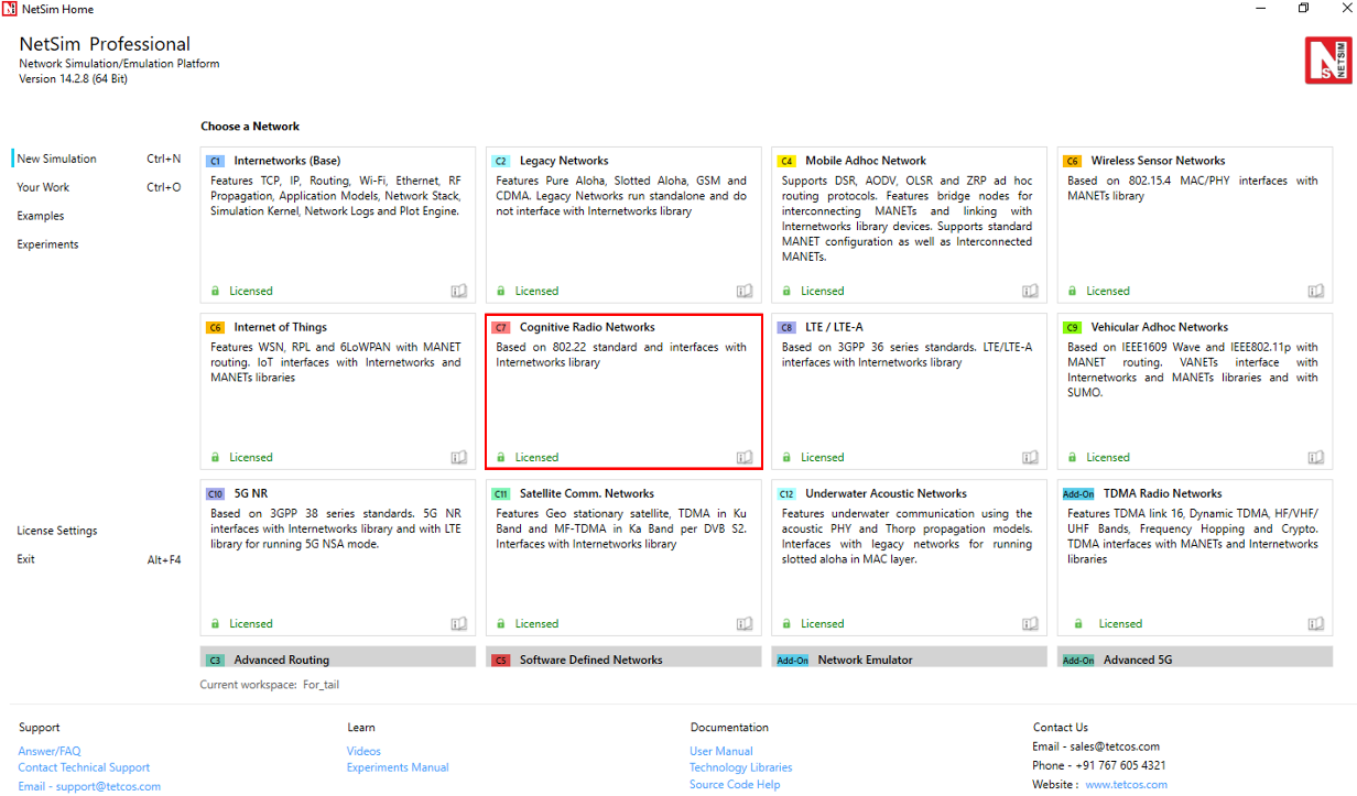
Open NetSim and click New Simulation \(\rightarrow\) Cognitive Radio Networks as shown Figure 1.
Create Scenario
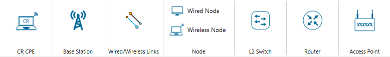
Cognitive Radio Networks come with a palette of various devices like CR CPE, Base Station L2 Switch, Router, Wired Node, Wireless Node, and AP (Access Point).
Click and drop into environment
Add a Base Station (BTS) – click the Base Station icon on the toolbar and place the BTS in the grid.
Add a Cognitive Radio CPE – click the CR CPE icon on the toolbar and place the CR CPE in the grid.
Add a Switch, Router, Wired Node, Wireless Node, and an Access point – click the appropriate icon on the toolbar and place the device in the grid.
NOTE: If you change the settings of the grid, then ensure that you place the CPE in the BS’s coverage area.
Connect the devices in the Cognitive Radio network by clicking the Wired/Wireless icon on the toolbar.
Configure an application as follows:
Click on the Set Traffic tab in the top ribbon/toolbar.
Select any application from the list and configure the traffic between source and destination.
Specify other application parameters per your model.
Set the properties of the BTS, CR CPE, and other devices as follows:
Click on a BTS, CR CPE, or device, then open the right-side properties panel and modify the interface and layer properties as per your requirements.
For a BTS, specify incumbent count, minimum and maximum frequency, channel bandwidth, modulation technique, coding rate.
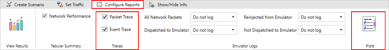
Enable Packet Trace, Event Trace (Optional)
Click Packet Trace / Event Trace icon in the tool bar and click on OK button. For detailed help, please refer to sections 8.3 and 8.4 of the User Manual. Select Plots icon for enabling Plots and click on OK button see Figure 2.
GUI Configuration Properties
| Parameter | Scope | Range | Description |
|---|---|---|---|
| MAC address | Fixed | The MAC address is a unique value associated with a network adapter. This is also known as hardware address or physical address. This is a 12-digit hexadecimal number (48 bits in length). | |
| Duplexing | Fixed | Duplexing in cognitive radio networks is crucial for efficient spectrum use and interference management, allowing secondary users to leverage TDD and FDD based on spectrum availability to communicate. | |
| Dsx Request Retries | Local | 1–7 | Number of Timeout Retries on DSA/DSC/DSD Requests. Dynamic Service Addition Requests. This message is sent either by a CPE or BS and is to create a new service flow. |
| Dsx Response Retries | Local | 1–7 | Number of Timeout Retries on DSA/DSC/DSD Responses. Dynamic Service Addition Responses. A DSA-RSP message shall be generated in response to a received DSA-REQ message. |
| T7 (S) | Local | 0–1 | Waiting Time for DSA/DSC/DSD Response timeout. |
| T8 (ms) | Local | 0–300 | Waiting Time for DSA/DSC Acknowledge timeout. Maximum 300 ms. DSA/DSC Acknowledges are sent in response to the DSA-RSP/DSC-RSP Messages. |
| T31 (ms) | Local | 1–16 | Waiting time for BLM-REP (Bulk Measurement Report) timeout. |
| Channel Check Time (s) | Local | 0–100 | The time during which a channel shall be checked for the presence of licensed incumbent signals having a level above the Incumbent Detection Threshold prior to the commencement of WRAN operation. |
| Non Occupancy Period (s) | Local | 1–60 | The required period during which WRAN device transmissions shall not occur in a given channel because of the detected presence of an incumbent signal in that channel above the Incumbent Detection Threshold. |
| Channel Detection Time (s) | Local | 0–2 | The maximum time taken by a WRAN device to detect a licensed incumbent signal above the Incumbent Detection Threshold within a given channel during normal WRAN operation. |
| Probability of false alarm | Local | 0 to 1 | Probability of false alarm denotes the probability of a CR user declaring that a Primary User is present when the spectrum is actually free. |
| Channel Move time (s) | Local | 0–2 | This is the time a WRAN system takes to stop all interfering transmissions on the current channel when it detects a licensed signal above the Incumbent Detection Threshold. |
| NUM Sensing Period | Local | 0–127 | The number of times a cognitive radio network will check for other signals (like licensed users) within a specific time window. |
| Sensing Period Duration | Local | 0–1023 | Duration of sensing period field (in units of OFDM symbols) in a Sensing Window Specification Array entry. |
| Sensing Period Interval | Local | 0–2047 | Sensing Period Interval is the time between each sensing check in a cognitive radio network. This interval determines how often the network pauses to listen for signals. |
| Candidate Channel Refresh Time | Local | 1–10 | Maximum time interval allowed before sensing is performed on the candidate channel to ensure that no incumbents are detected. |
| Backup Channel Refresh Time | Local | 1–10 | Maximum time interval allowed before sensing is performed on the backup channel to ensure that no incumbents are detected. |
| Candidate Channel Transition Time | Local | 1–100 | Minimum time duration without detection of any incumbent for a candidate channel to transition to the backup channel. |
| Wait Before Channel Move | Local | 1–4096 | Waiting time before which the BS moves to the first backup channel. This is used to make sure that all the CPEs are ready to move to the backup channel before BS switches operation. |
| Sensing Mode | Local | 0–2 | Specifies which SSF (Spectrum Sensing Function) outputs are valid and in some cases it specifies the behavior of the SSF. |
| ISO Country Code | Local | ISO Code of the Country. | |
| Incumbent Count | Local | 0–3 | It refers to the number of Incumbents. |
| Name | Fixed | Name of the incumbent (i.e., Primary user). | |
| ID | Fixed | Incumbent id is identification number of Primary user. | |
| Longitude/X-coordinate | Local | Less than the grid max value | The location of the device on the x-axis or horizontal axis in ‘Grid view’ and Longitude in ‘Map view’. |
| Latitude/Y-coordinate | Local | Less than the grid max value | The location of the device on Y-axis or vertical axis in ‘Grid view’ and Latitude in ‘Map view’. |
| Z Coordinate | Fixed | The location of the device on Z-axis. Note: Z-axis is non-editable parameter. | |
| Operating Frequency Start | Local | 54–862 | Frequency at which incumbent starts. |
| Operating Frequency End | Local | 54–862 | Frequency at which incumbent ends. |
| ON Duration | Local | 1–100000 | This represents how much time incumbent operates. |
| OFF Duration | Local | 0–100000 | Time gap between two successive incumbent operations. |
| Keep Out Distance (m) | Local | 1–500 | The maximum distance at which secondary user can detect the primary user. This is the distance between incumbent and the CR-CPE. |
| Operational Distribution | Local | Constant distribution: the output is constant value. Exponential Distribution: the output is a form of continuous probability distribution. | |
| Base station – Interface(Wireless) – Physical Layer | |||
| Channel bandwidth | Local | 6,7,8 | Frequency band used to transmit the data. Difference between Maximum frequency and Minimum frequency. |
| Sampling Factor | Fixed | 8/7 | This value, together with the bandwidth and the number of subcarriers used, helps determine the useful symbol time. |
| Modulation Technique | Local | QPSK, 16QAM, 64 QAM | Modulation is the process of varying one waveform in relation to another waveform. It is used to transfer data over an analog channel (i.e. radio link). |
| Coding Rate | Local | 1/2, 2/3, 3/4, 5/6 | It states what portion of the total amount of information that is useful (non-redundant). If code rate is k/n then for every k bits of useful information, the coder generates a total of n bits. |
| Multiple Access | Fixed | OFDMA is a frequency-division multiplexing (FDM) scheme utilized as a digital multi-carrier modulation method. | |
| Transmit Power (mW) | Local | 1–5000 | It is the signal intensity of the transmitter. The higher the power radiated by the transmitter’s antenna the greater the reliability of the communications system. Unit = mW. |
| FFT Size | Fixed | The effect of fast Fourier transform (FFT) size on detecting narrowband signals is analyzed and appropriate FFT size is suggested to improve the probability of detection. | |
| Cyclic Prefix Factor | Local | 1/4, 1/8, 1/16, 1/64 | Specifies the size of the cyclic prefix used by the PHY in the frame transmissions in this superframe. |
| Self-Coexistence | Fixed | No | A state by which wireless communication systems of the same type can share a RF transmission channel in a common area while minimizing harmful interference to each other. |
| DCD Interval | Fixed | 10 | Time between transmission of DCD messages. DCD Messages are regular updates sent by the base station to describe channel settings. |
| UCD Interval | Fixed | 10 | Time between transmission of UCD messages. UCD Messages are periodic messages sent by the base station to provide connected devices with information about upstream channel settings. |
| BW Req Backoff Start | Local | 0–15 | Initial size of BW Request opportunity used by CPEs to contend to send bandwidth requests to BS. |
| BW Req Backoff End | Local | 0–15 | Final size of BW Request opportunity used by CPEs to contend to send bandwidth requests to BS. |
| UCC Response wait time | Local | 2 | It is the waiting time of BS after it has sent the Channel Switch Request until it gets Channel Switch Response. |
| TTG (Transmit/Receive Transition Gap) | Fixed | 210 | TTG gap stands for Transmit Transition Gap. It is provided between downlink and uplink subframe. |
| Downlink to Uplink Ratio | Local | 1:1, 2:2, 3:3, 4:4 | It is the ratio of downlink to uplink transmission time. |
| Intra Frame Quiet Period Cycle Length | Local | 0–15 | Specified in number of superframes, it indicates the spacing between the superframes for which the intra-frame quiet period specification is valid. |
| Intra Frame Quiet Period Bitmap | Local | Length\(>\)0 | Valid only if Claimed Intra-frame Quiet Period Cycle Length \(>\)0. Each bit in the bitmap corresponds to one frame. |
| IFQP Duration (Symbols) | Local | 1–16 | Valid only if Claimed Intra-frame Quiet Period Cycle Length \(>\)0. Indicates the number of symbols starting from the end of the frame during which quiet period applies. |
| Reference distance (m) | Global | 0–10 | PL: is the path loss at the reference distance \(d_0\). Unit: Decibel (dB). See propagation model documents for details. |
| CR-CPE – Interface(Wireless) – Datalink Layer | |||
| BLM REP Retries | Local | 0–7 | Number of retries allowed for sending BLM-REP. |
| CR-CPE – Interface(Wireless) – Physical Layer | |||
| T20 (MACframes) | Local | 1–16 | Time the CPE searches for preambles on a given channel. |
| Antenna gain (dB) | Local | \(-\)1000 to 1000 | A relative measure of an antenna’s ability to direct or concentrate radio frequency energy in a particular direction or pattern. |
| Antenna height (m) | Local | 1 to 100 | Antenna height is only considered when using the following propagation models: Cost 231 Hata Urban, Cost 231 Hata Suburban, Hata Urban, Hata Suburban. |
Run Simulation
Click on Run Simulation icon on the top ribbon/toolbar.
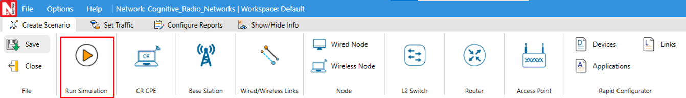
Set the Simulation Time and click on the Run button.